


Hey everyone! If you are not on Subscription with your AutoCAD Civil 3D, you should be. In the last few months some great Civil 3D content has been posted to the Subscription Center. Of course, the only way you can get to the content is to be on subscription and log in to the Subscription Center.
Here are descriptions for a couple of extensions that were added to the Subscription Center. The first is HEC-RAS Extension for AutoCAD Civil 3D 2009. This extension loads into your toolbox and allows you to export Civil 3D data such as cross sections into The US Army Corps of Engineers HEC-RAS software. Once your analysis is completed in HEC-RAS you can import the data back into Civil 3D. For those of you out there that perform flood analysis, this is an excellent tool.
The second is the Stage-Storage Extension for AutoCAD Civil 3D 2009. This extension also loads into your tool box. This extension will calculate volumes for detention/retention facilities with a few mouse clicks! You can then create a table with the incremental and cumulative volumes and then plug that information into the Hydroflow Hydrographs Extension for pond calculations.
There were several sub-assemblies that were posted to the Subscription Center also. These sub-assemblies included a Conditional Cut/Fill sub-assembly and a Crowned Lane sub-assembly that allows for independent slope control on sub-base. This is something that people dealing with Mississippi State Aid Projects have been asking for.
Again all of this content is available only to subscription customers. So, if you are not on subscription and you think that this content could be helpful in your every day routine, contact your reseller to get your subscription started! If you are already on subscription log on to the Subscription Center and download the content!
Friday, February 27, 2009


Monday, February 16, 2009
It Will Be Here Before You Know it!
The cold of February is beginning to pass and a hint of spring warmth is in the air, at least in some parts of this great nation. I spent this past weekend on Alabama's Gulf Coast with several thousand revelers where the festivities known as Mardi Gras originated. No, Mardi Gras didn't begin in New Orleans, it began in the city of Mobile, AL in 1703!
Anyway, as we attended parades over the weekend and had as pleasant of weather as I can remember in the last few years, I couldn't help but feel a little bit of excitement about the onset of spring in the southeast. Spring in the southeast is great, as the days get longer, the fish start to bite better and work becomes filled with the anticipation of the next release of our beloved Autodesk Software products.
I can't talk a whole lot about the new features in Civil 3D yet, but I can talk about some of the new features in AutoCAD 2010, and since Civil 3D is based on AutoCAD............
One of the new features for AutoCAD 2010 deals with pdf's. Yes, we have been asking to be able to use pdf's as underlays in our drawings and with the next release it will be possible. There are some cool features pertaining to the creation and use of pdf's in this release.
Keep tuned for more info on AutoCAD 2010 and AutoCAD Civil 3D 2010!
Anyway, as we attended parades over the weekend and had as pleasant of weather as I can remember in the last few years, I couldn't help but feel a little bit of excitement about the onset of spring in the southeast. Spring in the southeast is great, as the days get longer, the fish start to bite better and work becomes filled with the anticipation of the next release of our beloved Autodesk Software products.
I can't talk a whole lot about the new features in Civil 3D yet, but I can talk about some of the new features in AutoCAD 2010, and since Civil 3D is based on AutoCAD............
One of the new features for AutoCAD 2010 deals with pdf's. Yes, we have been asking to be able to use pdf's as underlays in our drawings and with the next release it will be possible. There are some cool features pertaining to the creation and use of pdf's in this release.
Keep tuned for more info on AutoCAD 2010 and AutoCAD Civil 3D 2010!
Wednesday, January 21, 2009
Vault or Shortcuts, You Decide
First things first. I have slapped my hand because I have not blogged in almost 3 months. Shame on me. I think I just got into a rut and had a little writer's block. So, with the next edition of our bi-monthly Alacad newsletter coming out in a few days I felt that writer's block or not I needed to get something posted.
Since I began working with Civil 3D with the 2006 release and I learned about Vault I have been a proponent of using Vault to store my projects. In fact, I convinced the Civil Department at my previous employer to try Vault. I even talked the IT Department into giving me a dedicated server for my Vault database and filestore. I still have a local install on my laptop for work that I use occasionally. Notice here that I said occasionally.
I am not as big a proponent of Vault as I used to be. Why? Good question. When I first started using Vault it was me, myself and I. I had full control of how my projects were set up and I knew what files I should keep or delete. I was the only one working in Civil 3D and storing files in the Vault. Life was good. Then we hired a new draftsman. Teaching him to use the Vault was not as easy. I also considerably more data to manage because there were two Vaulters now.
One of the things that I loved about Vault at the time was that I could create references to my data without having to do a whole lot. When I checked a drawing into the Vault, I was prompted to add the shortcuts or not. I typically created the shortcuts as needed and on occasion I would create all of the shortcuts, just in case I needed the information down the road. So, now you may be asking, "What data can I make Vault Shortcuts out of?" That list would include surfaces, alignments, pipe networks, etc. Again, life wasn't too bad at this point, but I did find myself using a lot more of my time trying to manage the data in my Vault.
So, I decided to try using the data shortcuts and references for a while. I could create the data shortcuts and store them in our project folder. This began to create a few issues. I had to store the data shortcuts in the project folder on our server, not on my local machine. This wasn't that big of a deal until I needed to take my computer home to work on a particular project. When I got home all I was able to see was a "Broken Reference." Now I am at home trying to be productive and I can't complete the tasks that I needed to complete that night. (we didn't have a VPN server at the time.)
Then I left for Alacad. I still had a few loose ends to tie up, so I continued using the same methodology for creating the shortcuts. I tried to keep them in the Project folder on my hard drive, so that when I took the projects back to the old company there would be no issues with the shortcuts. This was all fine and good until the project folder was moved to the file server and BAM!!!! All of the references were broken again.
Then I started working with AutoCAD Civil 3D 2009. Man, what a difference. The folks at Autodesk gave us some tools in 2009 that are second to none. Now I have a Project Template that reminds me a lot of the file structure in Land Desktop, so there was a familiarity there. they also gave us a program called Data Shortcuts Editor. This is the tool that I had been looking for! Now, if my Data Shortcuts get moved to a different location I can use the Data Shortcuts Editor to "remap" the location of the shortcuts and all is well with my drawing file. I can use the Find and Replace tool to find the Shortcuts' original location on my hard drive or server and replace that address with the new address and update my drawing file!
So, now that I have finished my narrative on using both vault references and data shortcuts, I'll challenge you to give them a try and see which works best for you. Until next time.
Since I began working with Civil 3D with the 2006 release and I learned about Vault I have been a proponent of using Vault to store my projects. In fact, I convinced the Civil Department at my previous employer to try Vault. I even talked the IT Department into giving me a dedicated server for my Vault database and filestore. I still have a local install on my laptop for work that I use occasionally. Notice here that I said occasionally.
I am not as big a proponent of Vault as I used to be. Why? Good question. When I first started using Vault it was me, myself and I. I had full control of how my projects were set up and I knew what files I should keep or delete. I was the only one working in Civil 3D and storing files in the Vault. Life was good. Then we hired a new draftsman. Teaching him to use the Vault was not as easy. I also considerably more data to manage because there were two Vaulters now.
One of the things that I loved about Vault at the time was that I could create references to my data without having to do a whole lot. When I checked a drawing into the Vault, I was prompted to add the shortcuts or not. I typically created the shortcuts as needed and on occasion I would create all of the shortcuts, just in case I needed the information down the road. So, now you may be asking, "What data can I make Vault Shortcuts out of?" That list would include surfaces, alignments, pipe networks, etc. Again, life wasn't too bad at this point, but I did find myself using a lot more of my time trying to manage the data in my Vault.
So, I decided to try using the data shortcuts and references for a while. I could create the data shortcuts and store them in our project folder. This began to create a few issues. I had to store the data shortcuts in the project folder on our server, not on my local machine. This wasn't that big of a deal until I needed to take my computer home to work on a particular project. When I got home all I was able to see was a "Broken Reference." Now I am at home trying to be productive and I can't complete the tasks that I needed to complete that night. (we didn't have a VPN server at the time.)
Then I left for Alacad. I still had a few loose ends to tie up, so I continued using the same methodology for creating the shortcuts. I tried to keep them in the Project folder on my hard drive, so that when I took the projects back to the old company there would be no issues with the shortcuts. This was all fine and good until the project folder was moved to the file server and BAM!!!! All of the references were broken again.
Then I started working with AutoCAD Civil 3D 2009. Man, what a difference. The folks at Autodesk gave us some tools in 2009 that are second to none. Now I have a Project Template that reminds me a lot of the file structure in Land Desktop, so there was a familiarity there. they also gave us a program called Data Shortcuts Editor. This is the tool that I had been looking for! Now, if my Data Shortcuts get moved to a different location I can use the Data Shortcuts Editor to "remap" the location of the shortcuts and all is well with my drawing file. I can use the Find and Replace tool to find the Shortcuts' original location on my hard drive or server and replace that address with the new address and update my drawing file!
So, now that I have finished my narrative on using both vault references and data shortcuts, I'll challenge you to give them a try and see which works best for you. Until next time.
Friday, October 31, 2008
An Update to Transparent Hatches
Hey everyone. Happy Halloween! I received a comment to the Transparent Hatches post from last month. After reading the comment, I tried to create the transparent hatch and plot it from my local printer. Much to my chagrin, the hatch that shows up transparent on the screen plotted a solid colr blob on my printer.
Well, that got me to thinking and doing some more research on the topic. I called on Alacad's resident Map 3D specialist James Murphy. I told James the steps that I had gone through to create the "transparent hatch." I asked him the all important question of how can I get this transpaernt theme to hatch. James informed me of a command that is new to the 2009 version of Map 3D, which means that it also works in Civil 3D. The command is MAPPLOTTRANSPARENCY. When you enter this on the command line you have the option to turn it on or off. Turn the command on. I sent the current drawing file to my local printer and lo and behold, the hatched area printed transparently! To get this to work on your local/network printer/plotter, you may have to adjust the line merge properties of the printer/plotter. This setting can be changed through the printer properties button on the plot screen. I hope this helps! Happy plotting!
Well, that got me to thinking and doing some more research on the topic. I called on Alacad's resident Map 3D specialist James Murphy. I told James the steps that I had gone through to create the "transparent hatch." I asked him the all important question of how can I get this transpaernt theme to hatch. James informed me of a command that is new to the 2009 version of Map 3D, which means that it also works in Civil 3D. The command is MAPPLOTTRANSPARENCY. When you enter this on the command line you have the option to turn it on or off. Turn the command on. I sent the current drawing file to my local printer and lo and behold, the hatched area printed transparently! To get this to work on your local/network printer/plotter, you may have to adjust the line merge properties of the printer/plotter. This setting can be changed through the printer properties button on the plot screen. I hope this helps! Happy plotting!
Thursday, October 9, 2008
A Couple of Things
Hey everyone! I've got a couple of things to talk about today. The first is Autodesk University 2008. The event will be held December 2-5, 2008 at the Venetian in Las Vegas. If you have never been, I suggest that you do everything possible to attend. Autodesk University (AU) is a meeting of the best and brightest Autodesk users from around the world. There are learning tracts for all industries including Civil and GIS. The classes are typically 90 mins long and some of them are actually hands on labs where you can work through exercises in the software. A lot of the classes will gain you some valuable Continuing Education credits!
The registration fee includes the cost of the conference, breakfast and lunch during the conference and Autodesk sponsored events during the evenings. The instructors are from Autodesk and Resellers across the country. In fact two of the presenters are from Alacad! Check it out. Here is the link: http://au.autodesk.com/
Okay, now for topic number two. I am currently trying to produce courseware for our surveying customers. I have not been able to locate any training materials that will help our surveyors in their day-to-day operations. If your company is willing to donate survey data to the cause please reply here and I will get back to you. I am in need of raw data files for traverses and topos.
The courseware that I am trying to write will cover data collection methods, using the Autodesk Field Book format to insert data and line work, or Field to Finish, creating plat maps, surfaces and the creation and use of parcels. These topics are what I see as the typical things that surveying customers are looking for. I am also open to further suggestions as to what this class should contain. Again reply to this post.
The registration fee includes the cost of the conference, breakfast and lunch during the conference and Autodesk sponsored events during the evenings. The instructors are from Autodesk and Resellers across the country. In fact two of the presenters are from Alacad! Check it out. Here is the link: http://au.autodesk.com/
Okay, now for topic number two. I am currently trying to produce courseware for our surveying customers. I have not been able to locate any training materials that will help our surveyors in their day-to-day operations. If your company is willing to donate survey data to the cause please reply here and I will get back to you. I am in need of raw data files for traverses and topos.
The courseware that I am trying to write will cover data collection methods, using the Autodesk Field Book format to insert data and line work, or Field to Finish, creating plat maps, surfaces and the creation and use of parcels. These topics are what I see as the typical things that surveying customers are looking for. I am also open to further suggestions as to what this class should contain. Again reply to this post.
Friday, September 19, 2008
Transparent Hatches
Hey folks! It has been a while again. I have been traveling quite a bit as of late and haven't taken the opportunity to write. I wanted to share something that I came across yesterday morning. I was trolling the Autodesk Civil 3D website and downloaded Luy Kuhn's "Tips and Tricks" webcast. While watching the webcast a support call came to mind. I received a call some time ago about creating transparent hatches. A customer had an aerial photograph that he had referenced into a drawing and was wanting to put some solid color fills in certain areas for a presentation he was doing. The problem was that the solid fill hatches came out as solid color blobs on his plot. Definitely not what he was looking for. We tried various things to get it to work to no avail. We finally gave up and decided that it couldn't be done very easily.
Well, have I got something for you! As I said I had been watching the webcast and Lucy decided to show how to create a transparent hatch. The method involves using the shrinkwrap command to create a closed polyline around a hatch pattern. Then the pattern is erased and the shapes are exported as SDF data. Using FDO Connect in Map 3D the data was queried into the drawing and a theme was applied to it. In Map 3D you can change the transparency of a theme by moving a slider bar! It was definitely easier than anything I had seen or tried.
If you want to see a clip of Lucy creating these transparent hatches peruse over to the Autodesk Civil 3D website and click on the Civil 3D Resource Center Link. You will have to register to view the content, but I think it will be worth it. There are other short vids of Lucy showing different functionalities of Civil 3D. A lot of information can be found there. Take a look when you get a chance!
Well, have I got something for you! As I said I had been watching the webcast and Lucy decided to show how to create a transparent hatch. The method involves using the shrinkwrap command to create a closed polyline around a hatch pattern. Then the pattern is erased and the shapes are exported as SDF data. Using FDO Connect in Map 3D the data was queried into the drawing and a theme was applied to it. In Map 3D you can change the transparency of a theme by moving a slider bar! It was definitely easier than anything I had seen or tried.
If you want to see a clip of Lucy creating these transparent hatches peruse over to the Autodesk Civil 3D website and click on the Civil 3D Resource Center Link. You will have to register to view the content, but I think it will be worth it. There are other short vids of Lucy showing different functionalities of Civil 3D. A lot of information can be found there. Take a look when you get a chance!
Friday, August 22, 2008
Those Pesky Pipe Slope Labels
Wow, has it been almost a month since my last post? Eh, life on the road! Anyway I was visiting with a customer yesterday who was somewhat aggrevated about the way Civil 3D labels pipes, inverts and slopes.
I tried to explain to him that the software is setup to compute pipe lengths and slopes based on the starting and ending points of the pipe. This means that the slope is computed from center of structure to center of structure. Being from the same geographical region as my customer and having dealt with most of the same regulating agencies, I felt his pain. You see, in our area the reviewing agencies require a 0.10' drop across a sanitary sewer manhole and 0.20' drop if the angle is 9o degrees. This drop across the manhole is measured from the invert of the pipe coming in to the manhole to the invert of the pipe going out of the manhole. I explained that Civil 3D, as well as all of the other civil engineering software packages that I have used in the past, calculate the slope of a pipe from the center of a structure to the center of the next structure. Herein lies the problem. The reviewing agencies look at the inverts and the lengths of the pipe and check the slope. Well, if I give them the length of pipe and it is the same as the distance between the manholes they start questioning the design. Or, if I give them the face to face length of pipe and the inverts, the slope doesn't match the computed value. So, what is the sloution?
After scouring articles and discussion groups on the internet I had decided that most of the people that had written on this subject had come up with the best solution. But as i met with my customer yesterday we had a little brain storm. Why not use an expression to calculate the desired slope? We tried it and, hey it worked! We got our desired results!
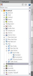
Here is what we did. Since the regulating agency expects to see the inverts, face to face pipe length and the slope we created an expression. I would suggest creating this expression in your standard template file so that you don't have to recreate it with each new project. First click on the Stettings tab in Toolspace. Then go down to Pipe and expand the node. Then expand the Label Styles node and expand the Plan Profile node. Here you will see an item called Expressions.
Right click on Expressions and select New. This will bring up a dialog box that looks similar to a scientific calculator. Be careful here when selecting a name for the Expression that you are
 creating. Once you create the the Expression, you cannot edit the formula or change the name. So, be careful and pay attention to what you are doing. For this expression, we chose a name of Slope face to face. Then we added the components to our expression. In the figure above you see the keypad that looks very similar to a calculator. To the right are two radio buttons. The first button is a list of available "variables" that can be used in your expression. The second button contains a list of mathematical fucntions that may be included in your calculations.
For our Expression we added in the the following formula:
({Start Invert Elevation}-{End Invert Elevation})/{2D Length - To Inside Edges}
Then we changed the Format result as: box to Percent, since that is the solution that we are looking for.
Once the expression is created you have to go into your Pipe Label Style and change the style to contain the new "Slope face to face" label and change the pipe length to the 2D - inside edge to inside edge. This should fix the label issue. The only issue that remains, and I haven't come up with a solution for it yet, is that in the profile view, if you measure from the point of intersection of the inside pipe diameter line and the side of the box to the nearest grid line and calculate that elevation, the elevation of the pipe will be off by a couple of hundredths for flat slopes. This should not be an issue since this is a graphical representation.
Have fun with Pipes!
Subscribe to:
Posts (Atom)