So, let's see how we would do just that. First, I created a point in my drawing. I did not change the default settings so when the point was created all I got was the point marker. Next I applied a Point Label Style to the point. the screen cap below shows my point style and point marker style.

Next, I clicked on the point to activate the grips and drug the label up and to the right of my point as shown below.
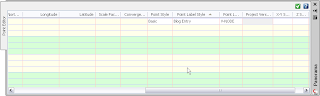
 From here, obviously, we need to edit the point label style. You can do this by clicking on the Settings tab in Toolspace and then expanding the Points node and then expanding the Label Styles node and then right-clicking on the style and selecting edit. Alternatively, you can right click on the point that you want to edit and in the Edit Points Vista, scroll to the right until you see the Point Label Style column. Clicking in the Point Label Style column will bring up the select label style dialog where you can edit the style by clicking on the button to the right of the style field.
So, we have obviously applied colors to the text components on the layout tab. But, as shown above the colors are changed to the "Byblock" default color for the Dragged State. Here we will click in the Text Contents field to bring up the Text Component Editor and we want to highlight the text in the right-hand side of the editor. Then we will click on the Format tab and set the color of the text.
 We want to do this for each of the components in our label style. Then we will click on the Dragged State tab and make sure that the Dragged State Component Display is set to Stacked Text.

The results of our point label style are shown below. This is what the Dragged state would look like if we had set the Dragged State Component Display to "As Composed" also.
 So, let's edit the point label style again. And this time on the Dragged State tab, let's change the attachment point of the leader to the Middle of the Top Line.

Click OK. You may have to regenerate the screen to see that the changes did take affect. You should be left with something that looks like the image below. Now, here are a couple of hints for those of you working with Label Styles. The steps above will work for any Dragged State. You may want to create a Right and Left dragged state if you want a different connection point for the leader depending on which side of the object you are dragging the label. Also, pay attention to the order in which your components are created in the label style. The Dragged State arranges the text components in the order in which they were created!
 We want to do this for each of the components in our label style. Then we will click on the Dragged State tab and make sure that the Dragged State Component Display is set to Stacked Text.
The results of our point label style are shown below. This is what the Dragged state would look like if we had set the Dragged State Component Display to "As Composed" also.
 So, let's edit the point label style again. And this time on the Dragged State tab, let's change the attachment point of the leader to the Middle of the Top Line.
Click OK. You may have to regenerate the screen to see that the changes did take affect. You should be left with something that looks like the image below.
 Now, here are a couple of hints for those of you working with Label Styles. The steps above will work for any Dragged State. You may want to create a Right and Left dragged state if you want a different connection point for the leader depending on which side of the object you are dragging the label. Also, pay attention to the order in which your components are created in the label style. The Dragged State arranges the text components in the order in which they were created!

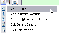 This will bring up the Label Style Composer Dialog box. On the Information tab give your new style a name. Click on the General Tab. Here you can set the text style, visibility and layer for you new point label style. (Hint: In 2009 the Standard Text Style maps to the Simplex font.) Next click on the Layout Tab. This is where all of the fun begins! The very first thing that you will see is a pull down menu called Component Name. To the right there are four buttons. These buttons are: Create Component, Copy Component, Delete Component and Component Draw Order. Click on the Create Component pull-down. You have options for creating text, line and block components. Choose Text to create a text component. Since we are dealing with Point Label