on the down arrow beside Alignment on the Create Design Panel.
Let's take a look at some other new features of Civil 3D alignments. Have you ever been working on a transportation project that had multiple lanes and transition regions all over the place? It has been a while since I was in that situation, but I do remember those days. We created our center line alignment and then used offset to create the edge of pavement and then created another offset for the transition region and applied fillets and tangents to tie them together. Alas, the boss comes in after a meeting with the powers that be and says that the center line is shifting and we have to have the changes by 9:00 am tomorrow morning. Time to hit the panic button, right?
The 2010 release of Civil 3D has several tools to help in these situations. Let's take a look at the Prospector Tab in Toolspace. As seen below, Alignments now have more categories or classifications. So, what does this do for us? Notice the second classification is Offset Alignments.

Now we can create offset alignments from our center line alignment and the offsets will stay dynamically linked to the center line. Can you think of any useful applications for this?
Another new feature for alignments is Widening. Using the widening functionality the designer or engineer can easily create a widened section in his 2D layout. widening works by creating regions along the offset alignment where the user can specify a different offset for one region to create a turn lane, for instance. On top of creating the widened section, the user can specify the geometry to use in transition between the two regions.
There is other new functionality associated with alignments. We will take a look at those next time.


 We know that this is not correct. So, how do we fix it? It just
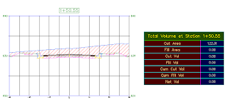
 Here we can see that the Datum surface more closely resembles how a contractor would construct our roadway with a 1 foot extension of the sub-base under our curb and gutter.Now lets talk about material and earthworks volumes based on our cross sections. We are going to assume that at this point that we have created our cross sections from the alignment associated with our corridor model and that we have created multiple cross section views on a D-size sheet. At this point we realize that we forgot to add the volume tables to our cross sections. Can we fix this rather easily? You bet we can.
 At this point I will edit the Material List Criteria to make sure that have the materials listed that I am interested in, such as Pave1, Pave2, Base and Sub-base. After setting the materials that I want I click on OK to close the Compute Materials dialog. Next I go back to the Sections menu and select Compute Materials again.
 I want to click on the Import another criteria. This will allow me to add additional criteria to the current materials list. Here I want to select Earthworks so that we can calculate the cut/fill volumes at each section.
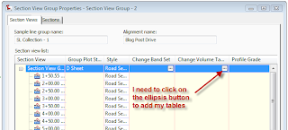
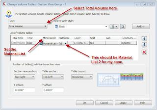 Then click on