


Friday, May 14, 2010
This Blog Has MOVED!!!!!!!!!!
Hey everyone! I have decided to relocate this blog to a new location. The new location is http://gettingtothedirt.wordpress.com. You will have to register for an account at Wordpress if you want to leave a comment on the blog page, but the account is benign. I have had one for a while and have never received any spam or junk mail from my account there. Come on over and check out the new digs!


Monday, May 10, 2010
The Conditional Subassembly - Could it be Right for You?
I want to start this post by giving credit to Jason Hickey at Autodesk Support for suggesting that I look into the use of the Conditional Subassembly when trying to assist one of my customers a couple of weeks ago. I have to say what an asset Jason and the rest of the Civil 3D support team are! Thanks guys.
 The hardest thing to overcome when using the conditional subassembly is that the subassembly requires a Length and Slope as parameters. The length and slope are only used to place the conditional subaseembly and any subassemblies to be applied for that condition graphically on the screen, instead of having all of them stacked on top of each other. This makes selecting and editing the individual conditions easier for the user. Again, these length and slope parameters are not specifying a length and slope from the attachment point to a point where the subassemblies will be applied, but just placing them on the screen. The subassemblies will be applied at the connection point of the conditional subassembly.OK, now that I have described the conditional subassembly, let's take a look at how we can apply it. Let's assume that we have a roadway that we are designing or needing to model. We will build an assembly as usual, but when we get out to the daylight area we will have a couple of decisions to make. Let's assume that along our roadway if we have to cut more than three feet from the elevation at the edge of the outside boulevard of the sidewalk that we will be required to construct a retaining wall along our roadway. If we were to design this roadway without using the conditional assembly, it is conceivable that we could do this with one assembly, assuming that the height of wall and amount of cover are adjusted so that the retaining wall subassembly is not applied in areas where our cut is less than 3 feet from the outside boulevard elevation.
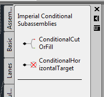
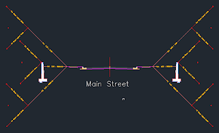
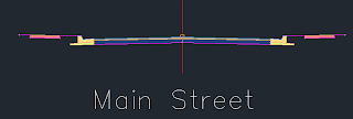 Our assembly should resemble the image above. Now will will add the first conditional cut/fill subassembly to the right side. On the tool palette click on the conditional tab and then select the ConditionalCutOrFill subassembly. The Properties dialog will open and look something like this: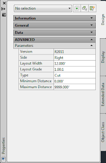
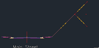 Next we will add the condition for our retaining wall and the fill condition. When you are trying to figure out what the Layout Length and Layout Grade needs to be for your conditional subassembly, if it is a cut situation the parameters input will place the conditional subassembly above a horizontal projection from the connection point. If it is a fill condition that you are establishing, it will place the conditional below the horizontal projection from the connection point. So, after adding in the conditional subassemblies and copying all of the assemblies to the left side of our Assembly, we should have something like this:

So, what is this Conditional Subassembly anyway? Well, if you ever had a course in computer programming you may remember the "If, Then" statement that placed conditions on your routine. (i.e. If x>0, then y=3x^2...) The Conditional Subassembly does the same thing for your Assembly and corridor model. The Conditional Subassembly comes in two varieties, one that targets horizontal alignments while the other targets cut/fill situations. (Note: for the rest of this post we will be looking at the Conditional Cut/Fill Subassembly.) There is no limit to the number of Conditional Subassemblies that can be applied to the Assembly. One of the neat things that you can do with this subassembly is apply it to other conditional subassemblies.
So, with a little planning and forethought upfront, you may be able to model a corridor with 1 or 1 assemblies instead of 5 or 6 or more. If you are an outside the box kind of thinker, then the possibilities of applying the conditional subassembly could be endless.
The hardest thing to overcome when using the conditional subassembly is that the subassembly requires a Length and Slope as parameters. The length and slope are only used to place the conditional subaseembly and any subassemblies to be applied for that condition graphically on the screen, instead of having all of them stacked on top of each other. This makes selecting and editing the individual conditions easier for the user. Again, these length and slope parameters are not specifying a length and slope from the attachment point to a point where the subassemblies will be applied, but just placing them on the screen. The subassemblies will be applied at the connection point of the conditional subassembly.OK, now that I have described the conditional subassembly, let's take a look at how we can apply it. Let's assume that we have a roadway that we are designing or needing to model. We will build an assembly as usual, but when we get out to the daylight area we will have a couple of decisions to make. Let's assume that along our roadway if we have to cut more than three feet from the elevation at the edge of the outside boulevard of the sidewalk that we will be required to construct a retaining wall along our roadway. If we were to design this roadway without using the conditional assembly, it is conceivable that we could do this with one assembly, assuming that the height of wall and amount of cover are adjusted so that the retaining wall subassembly is not applied in areas where our cut is less than 3 feet from the outside boulevard elevation.But, our goal here is to make this as simple as possible. By applying the conditional subassembly we can define what happens in areas of cut from 0.00' to 3.00' above the outside boulevard elevation and then again for anything above 3.00' of cut. We will also define what happens in the fill situation. The roadway will be a typical two-lane road using the LaneOutsideSuper and UrbanCurbGutterGeneral subassemblies. We will then apply the UrbanSidewalk subassembly with an inside boulevard of 2.5', sidewalk width of 4', depth of 4", an outside boulevard width of 1.5' and a slope of 2%.
Our assembly should resemble the image above. Now will will add the first conditional cut/fill subassembly to the right side. On the tool palette click on the conditional tab and then select the ConditionalCutOrFill subassembly. The Properties dialog will open and look something like this:Notice the parameters for Layout Width and Layout Grade. These are the parameters that are going to locate the Conditional Cut or Fill subassembly in relation to the edge of the outside boulevard of our sidewalk subassembly. We are going to enter a Layout Width of 20 and a Layout Grade of 1:1. Then we will change the Maximum Distance to 2.99' and attach this subassembly to the marker at the right edge of the Outside Boulevard. Then we will add the BasicSideSlopeCutDitch Subassembly to the end of the CondtionalCutOrFill Subassembly after changing the parameters for the Cut Ditch subassembly by reducing the Foreslope and Backslope widths to 0.00 and the slope for the Cut to 3:1. The result looks like this:
Next we will add the condition for our retaining wall and the fill condition. When you are trying to figure out what the Layout Length and Layout Grade needs to be for your conditional subassembly, if it is a cut situation the parameters input will place the conditional subassembly above a horizontal projection from the connection point. If it is a fill condition that you are establishing, it will place the conditional below the horizontal projection from the connection point. So, after adding in the conditional subassemblies and copying all of the assemblies to the left side of our Assembly, we should have something like this:Now we can create our corridor model and set the target for all of the daylight assemblies to Existing Ground. There may be a need to change how often the assembly is applied to the corridor to help get an accurate location for the transition from from a cut slope to the retaining wall. If you have those stations established, you could just add them in as supplemental stations.
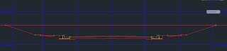
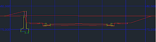
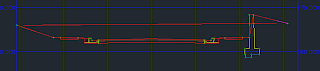
After the corridor has been created, we can look at the corridor sections to see if the corridor model applied the conditions correctly. Below are some screen captures from the station immediately prior to transitioning to the retaining wall and from the retaining wall to a cut section.
Happy Modeling!
Monday, March 29, 2010
AutoCAD Civil 3D 2011
Last week Autodesk officially announced its 2011 portfolio of products. Some of those products are available on the Subscription Center. With this year's releases, downloading from the Subscription Center is the primary way to get you software now. But, you can click on a link there and request media.
Now, I don't have a lot of time this morning but, I want to leave you with one thing about the upcoming release...........64-bit! Yes, that is right. This year's release of AutoCAD Civil 3d will be released in 32-bit and 64-bit.
I will be posting some more information in the coming days.
Now, I don't have a lot of time this morning but, I want to leave you with one thing about the upcoming release...........64-bit! Yes, that is right. This year's release of AutoCAD Civil 3d will be released in 32-bit and 64-bit.
I will be posting some more information in the coming days.
Thursday, December 10, 2009
1 Day Grading Course in Madison, MS
Hey everyone! I just wanted to let you all know that ALACAD will be having a 1-day Grading Course on January 28, 2010 in our Madison, MS office. Space is limited and is first come first served. For more information follow this link!
Here is a brief description of the class.
Here is a brief description of the class.
This 1-day course will cover several options for grading and show the user how to utilize the different grading techniques to their advantage. Grading in Civil 3D is probably one of the most powerful functionalities in the software, but is also one of the least understood.
This course will begin with a discussion of some basic properties of a surface in Civil 3D and how to modify the surface. This will include a discussion on the methodology Civil 3D uses for creating a TIN. In addition, we will cover the definition and use of Feature Lines. Finally, we will look at some methods for creation grading plans, or finished grade surfaces using the different tools at our disposal.
Thursday, October 22, 2009
Autodesk Releases Subscription Advantage Packs for Many Software Titles
Does it really pay to be an Autodesk Subscription Customer? After a brief review of the Subscription Advantage Packs released yesterday I believe the answer has to be a resounding, "YES!!!!!!!" The Advantage Pack for Civil 3D 2010 has many tools that will help increase productivity and efficiency. Let's take a look at some of the new tools that are in the Advantage Pack.
The tools are organized into groups in the Subscription Extension Manager on the Toolbox tab in Toolspace. The first category is for Alignments. There are 2 tools here. The first will allow the user to create a new alignment from an existing alignment and add data to the newly created alignment. (Think rail switches.) This tool can be used in other ways such as creating alternative alignments that have common tie-ins. The next tool for alignments is a routine that will create a best fit alignment from point data. Invoke the routine and pick a point group and you are off to the races! You will be shown a report of the best fit analisys.
The next category contains some inquiry tools for computing minimum distances between entities and surfaces and vertical distances between entities.
Next is Point Clouds. Finally Civil 3D has tools to allow us to harness LiDAR data! The Point Cloud routine will allow you to create a Point Cloud database (.isd format) from data in several different formats. Once the database is created you can recall the point cloud database using the same wizard from the Toolbox tab in toolspace. You can stylize the point cloud to show the information that you want to see and then you can also remove the Civil 3D settings from the point cloud so that the data can be used as a default subset of points.
The next group is for points. The new tool here is not really new, but there is a zoom to command here that allows you to input the point number without having to find the point in a point group first. The really cool thing is that this command can be run as a transparent command!
The Profile group has a routine for creating a best fit profile from COGO point data, surface profiles, feature lines or AutoCAD 3D polylines, points or blocks.
The next tool is for laying out Roundabouts. This routine has a wizard that asks for design criteria and then lays out the roundabout for you based on the alignment geometry and data input into the wizard.
There are some other tools that I will let you discover on your own. So, If you are a Subscription customer, go to the Subscription Center and download the Advantage Pack today. I think it is well worth it. While you are there, watch the video clip. It gives an overview of some of these tools in action. If you are not a Subscription member, call your Reseller today and purchase your annual Subscription to Civil 3D so that you can have access to these great new tools too!
The tools are organized into groups in the Subscription Extension Manager on the Toolbox tab in Toolspace. The first category is for Alignments. There are 2 tools here. The first will allow the user to create a new alignment from an existing alignment and add data to the newly created alignment. (Think rail switches.) This tool can be used in other ways such as creating alternative alignments that have common tie-ins. The next tool for alignments is a routine that will create a best fit alignment from point data. Invoke the routine and pick a point group and you are off to the races! You will be shown a report of the best fit analisys.
The next category contains some inquiry tools for computing minimum distances between entities and surfaces and vertical distances between entities.
Next is Point Clouds. Finally Civil 3D has tools to allow us to harness LiDAR data! The Point Cloud routine will allow you to create a Point Cloud database (.isd format) from data in several different formats. Once the database is created you can recall the point cloud database using the same wizard from the Toolbox tab in toolspace. You can stylize the point cloud to show the information that you want to see and then you can also remove the Civil 3D settings from the point cloud so that the data can be used as a default subset of points.
The next group is for points. The new tool here is not really new, but there is a zoom to command here that allows you to input the point number without having to find the point in a point group first. The really cool thing is that this command can be run as a transparent command!
The Profile group has a routine for creating a best fit profile from COGO point data, surface profiles, feature lines or AutoCAD 3D polylines, points or blocks.
The next tool is for laying out Roundabouts. This routine has a wizard that asks for design criteria and then lays out the roundabout for you based on the alignment geometry and data input into the wizard.
There are some other tools that I will let you discover on your own. So, If you are a Subscription customer, go to the Subscription Center and download the Advantage Pack today. I think it is well worth it. While you are there, watch the video clip. It gives an overview of some of these tools in action. If you are not a Subscription member, call your Reseller today and purchase your annual Subscription to Civil 3D so that you can have access to these great new tools too!
An Update to AutoCAD Civil 3D 2010 and Windows 7
It has been a little over 2 weeks since upgrading my OS to Windows 7. So far I have not run into any issues when working in AutoCAD Civil 3D. The software seems to load quicker and respond quicker in most cases. I have had two crashes since installing OS. The first was a BSOD, but I was pushing the OS with Civil 3D, several Office programs, IE and a couple of Virtual Machines running. As best I could tell the crash was actually caused by a driver that I hadn't updated. After updating the driver the only other crash was actually in Civil 3D, but could be attributed to User Error!
Tuesday, October 6, 2009
Civil 3D and Windows 7
Ok.....I believe in living on the bleeding edge! Last night I decided to install Windows 7 and see what happened. So far, so good. The only thing that I found was something that has been going on for a while. If you prefer to use Firefox as your web browser, you will probably not be able to have the reporting feature in Civil 3D open directly in the browser. This is an old issue. I tried to set IE as the default browser and map .htm and .html files to Firefox, but I still kept getting an error. As soon as I deleted Firefox I was able to get the reports to open in a browser window. Not sure that I am happy about that. I kinda like Firefox. The other option is to create a shortcut on your desktop that maps to the CivilReport.html file so that you can run the report and then click the shortcut and have it open in Firefox. Just a couple of more clicks I guess, but I would like to be able to use whatever browser I choose.
Can you really see through Transparent Commands?
While working on a support call today, I derived a solution for a customer that included using a Transparent Command. That got me to wondering how many people actually use the Transparent Commands in Civil 3D. I know that I did not use them very often in past employment engagements. It was not until I started teaching classes on Civil 3D that I fully understood the power of these commands and how they could help me work smarter and not harder.
For example, at one of my past jobs I worked with an older gentleman who was very close to retirement. He was fairly proficient with vanilla AutoCAD, but almost completely illiterate when it came to Civil 3D. I am not knocking the guy, because he was good at what he did. He just did not see the need to learn new software while being on the verge of retirement. A typical scenario for one of his projects was that I would take the survey data and create the surface and then hand the drawing off to him. He would complete the geometric design and give it back to me to produce profile drawings. When I created the profile drawings, I would have to plot them at an exaggerated scale and he would break out his old HP Calculator, complete with card reader, and design the profile on paper.
Then he would had the paper copies back to me and I would input the data into Civil 3D and finalize most of the design before handing it back for his review. At the time, I did not use the Transparent Commands very much because I did not understand what they were. So to input his design data, I would create a layout profile and get the PVI's close to their desired locations and elevations. Then I would open up the profile editor and hand correct the stations and elevations.
Does this sound familiar to you? Well, after a while I learned that there were commands in Civil 3D that run "inside" of other commands and allow us to input specific data in that command. Instead of having to get the PVI's close, I could have used the Profile Station Elevation transparent command to specifically enter the station and elevation of the PVI without having to go back and edit.
Which brings me back to today's case. The customer was working on a paving project. A contractor had constructed a leveling course and the customer had sent his crew out to collect profile elevations at an offset left and right of the center line. He then wanted to show those offsets in his profile view. I didn't want to have to try and create another surface and extract the data from the surface when we already had the point information in the drawing.
I began looking for a Transparent Command that would let me harness that point information and apply it in the profile view. To both the customer's satisfaction and mine I found the transparent command that would allow us to do just that. The command was Profile Station and Elevation from a Cogo Point, or 'SPE.
To use the command we went to the Ribbon and selected Profile Creation Tools from the Create Design panel. Once we entered the profile name in the dialog box and set our styles we invoked the Create Tangents command and then invoked the 'SPE transparent command. We selected the profile view in which to draw the profile and began to pick the point objects we wanted to see in the profile view. Then the steps were repeated for the opposite offset.
If you have not looked into using Transparent Commands, I encourage you to look into them. They can definitely help us work smarter and not harder!
For example, at one of my past jobs I worked with an older gentleman who was very close to retirement. He was fairly proficient with vanilla AutoCAD, but almost completely illiterate when it came to Civil 3D. I am not knocking the guy, because he was good at what he did. He just did not see the need to learn new software while being on the verge of retirement. A typical scenario for one of his projects was that I would take the survey data and create the surface and then hand the drawing off to him. He would complete the geometric design and give it back to me to produce profile drawings. When I created the profile drawings, I would have to plot them at an exaggerated scale and he would break out his old HP Calculator, complete with card reader, and design the profile on paper.
Then he would had the paper copies back to me and I would input the data into Civil 3D and finalize most of the design before handing it back for his review. At the time, I did not use the Transparent Commands very much because I did not understand what they were. So to input his design data, I would create a layout profile and get the PVI's close to their desired locations and elevations. Then I would open up the profile editor and hand correct the stations and elevations.
Does this sound familiar to you? Well, after a while I learned that there were commands in Civil 3D that run "inside" of other commands and allow us to input specific data in that command. Instead of having to get the PVI's close, I could have used the Profile Station Elevation transparent command to specifically enter the station and elevation of the PVI without having to go back and edit.
Which brings me back to today's case. The customer was working on a paving project. A contractor had constructed a leveling course and the customer had sent his crew out to collect profile elevations at an offset left and right of the center line. He then wanted to show those offsets in his profile view. I didn't want to have to try and create another surface and extract the data from the surface when we already had the point information in the drawing.
I began looking for a Transparent Command that would let me harness that point information and apply it in the profile view. To both the customer's satisfaction and mine I found the transparent command that would allow us to do just that. The command was Profile Station and Elevation from a Cogo Point, or 'SPE.
To use the command we went to the Ribbon and selected Profile Creation Tools from the Create Design panel. Once we entered the profile name in the dialog box and set our styles we invoked the Create Tangents command and then invoked the 'SPE transparent command. We selected the profile view in which to draw the profile and began to pick the point objects we wanted to see in the profile view. Then the steps were repeated for the opposite offset.
If you have not looked into using Transparent Commands, I encourage you to look into them. They can definitely help us work smarter and not harder!
Monday, September 14, 2009
A Couple of Pointers on Pipes
Have you ever needed to modify, or add part sizes to a structure in AutoCAD Civil 3D? Well, in this post I am going to cover how to modify and/or add part sizes in the parts catalog. The first thing I will tell you is that I am no expert in creating parts via the Part Builder in Civil 3D, but I have learned how to modify some of the parameters for existing parts to get the sizes that I need.


After clicking on Modify Part Sizes Part Builder opens to show the parametric model of the structure and a list of the parameters used to define the structure.
 On the right hand side of the Part Builder screen we see an image of the part. The part may or may not be drawn to any particular scale in this area. It really doesn't matter as we are going to assign the values for the parameters that we want anyway. On the left hand side we see a tree that contains listings of the parameters used to create the part along with definitions for geometry and constraints.

Next move over to the SIL column and repeat the above steps to add a par size of 52.0000 inches. Then check the WTh column and make sure that there is a 8" Wall thickness in the list. Next we need to look at how we are able to add a part with the dimensions that we just created to our parts list. We need to make sure that the wall thickness can be assigned to the new structure from the list of wall thicknesses that are in the list.
So, let's say, for instance, that you need a rectangular junction structure that measures 4' x 5' outside box dimensions and is traffic bearing (8" min wall thickness). How would we go about adding that part size to the current parts catalog? The first thing that we need to do is open up Part Builder. (Note: all of the Screen Captures in this post are from AutoCAD Civil 3D 2010.) The screen cap below shows where to find Part Builder on the Ribbon.
So we open Part Builder and on the Getting Started Dialog box we select what type of part we want to modify. In this case, I am choosing the rectangular structure with circular frame. Then we click on Modify Part Sizes as shown below.
After clicking on Modify Part Sizes Part Builder opens to show the parametric model of the structure and a list of the parameters used to define the structure.
On the right hand side of the Part Builder screen we see an image of the part. The part may or may not be drawn to any particular scale in this area. It really doesn't matter as we are going to assign the values for the parameters that we want anyway. On the left hand side we see a tree that contains listings of the parameters used to create the part along with definitions for geometry and constraints.If you expand the Size Parameters node in the tree, you will see a list of the different parameters that make up the dimensions of the structure. Notice in the list that there are parameters for the Inside Width (SIW) and the Inside Length (SIL). These are the two parameters that we want to change for our new structure. We may also have to associate the two dimensions with the Wall Thickness (WTh). We can add or modify the appropriate parameters by right-clicking on Size Parameters and selecting edit values from the pop-up menu. This will open up the Edit Part Sizes dialog box.
Now remember, our intent here is to add a part size that will correspond to the desired dimensions of the structure we are calling for in our design, a 4'x5' box with 8 inch walls. We need to look at the available part sizes in the list to see if we need to add a size or modify an existing one. In this case click in the cell for SIW, then click on the Edit Sizes button (2nd from left at the top of the dialog box). This brings up another dialog box with all of the sizes that have been input for this parameter. Notice that there is not a 40 inch measurement, so we will have to add that one. Click the add button and a new field is created at the bottom of the list. Type in the value, in our case 40.0000. The unit of inches is the default here.
Next move over to the SIL column and repeat the above steps to add a par size of 52.0000 inches. Then check the WTh column and make sure that there is a 8" Wall thickness in the list. Next we need to look at how we are able to add a part with the dimensions that we just created to our parts list. We need to make sure that the wall thickness can be assigned to the new structure from the list of wall thicknesses that are in the list.
Click on the drop down in the middle of the top row of buttons in the dialog box. Then select Parameter Configuration from the list. The Data Storage row should be set to list for the three parameters that we have looked at above. Once this is done, click OK to close the dialog box and then click on the disk icon in the upper left hand corner of the Part Builder. This saves he new part parameters. Now we can close part builder. After closing Part Builder, we need to type "partcatalogregen" on the command line to update our part catalog with the new parameters. Now we edit our parts list and select the appropriate part sizes from the lists for SIW, SIL and WTh.
Another little tidbit that some users have seemed to forgotten. When showing a crossing pipe in a profile view, create a style with crossing pipe in the title and switch on the crossing components on the Profile tab in the view directions box on the display tab. This will cause the pipe to show a a section in the profile view.
Tuesday, August 25, 2009
SASHTO 2009 Biloxi, MS
Hey just wanted to let everyone know that ALACAD will be at this year's SASHTO event at the Beau Rivage in Biloxi, Mississippi, August 31-September 2, 2009. If you are attending the event, please stop by our booth and say, "Hi!" We look forward to seeing you there!
Wednesday, August 12, 2009
From the Guys at Autodesk Support: Understanding Performance Using Civil 3D
The guys at Autodesk Support have released their monthly video on their YouTube channel. This time the video is on understanding the performance of Civil 3D. The video discusses RAM, Operating Systems and other performance related issues. So, if you are wondering how Civil 3D interacts with the system memory or operating resources this video may be of interest to you. You can check it out here.
I am in the process of becoming more familiar with AutoCAD Raster Design. So, in my next posts I may be discussing some of the features of Raster Design and how you can benefit from this piece of software.
I am in the process of becoming more familiar with AutoCAD Raster Design. So, in my next posts I may be discussing some of the features of Raster Design and how you can benefit from this piece of software.
Monday, August 3, 2009
Update 1 for AutoCAD Civil 3D 2010 and AutoCAD Civil 2010
Hey everyone. I spent the end of last week at the ASCE Alabama Chapter Summer Meeting. Thanks to all of those who stopped by to say "Hi," or asked other questions. While at the conference, I missed the release of Update 1 for both Civil and Civil 3D. The updates were released on July 31st.
Anyway, for those of you who are looking for a link to the updates:
AutoCAD Civil 3D 2010: Download here.
AutoCAD Civil 2010: Download here.
Until next time!
Anyway, for those of you who are looking for a link to the updates:
AutoCAD Civil 3D 2010: Download here.
AutoCAD Civil 2010: Download here.
Until next time!
Wednesday, July 22, 2009
Another Round with Dragged State Labels
Yesterday, while at a customer's office I noticed something that I had not seen before when it comes to dragged state labels, with points anyway. Take a look at the image below. I have created to random points in a drawing with the Point Marker Style for each set to Basic and the Point Label Styles are Point#-Elevation-Description and a style the I created with the coordinate information in it.
 So, as you can see I have changed the colors of the text and added the coordinates. But then we looked at the dragged state for the point with the OOTB Point#-Elevation-Description Label Style. I was showing the customer how the label reacted when it was dragged out from the point. The customer asked the obvious question about the location of the leader in the dragged state and wanted the leader attached to the middle of the top line of text. This is where something interesting happened. When I changed the display of the dragged state from "As Composed" to "Stacked Text", the elements of the labels where rearranged. I had not noticed this in previous versions and that was probably because I typically used the Dragged State in the As Composed display mode.

As you can see from the shot above, the the dragged state is what we would expect in a point label of this variety. Sometimes it is the little nuances of Civil 3D that make you go hhhmmmm.
I started digging in to see if I could deduce what had happened. The conclusion that I came to was that the Stacked Text display mode uses the order in which the label components are created. The next screen capture will show what I mean.
 You will notice here that the component names are listed in the following order: Point Description, Point Number and Point Elev. And looking back at the label in a dragged state with the display mode set to "Stacked Text" we see that the label has been adjusted to match the order shown in the Label Style Composer.
To prove my theorem, I created a style the contained the same information and added the coordinate data. I was careful that I created the label components in the order that I wanted them to be displayed in the stacked text display mode. The result was as expected.

As you can see from the shot above, the the dragged state is what we would expect in a point label of this variety. Sometimes it is the little nuances of Civil 3D that make you go hhhmmmm.
Friday, June 12, 2009
Brought to You by the Fine Folks at Auotdesk Support
I was looking at different Civil 3D blogs a few weeks back and found one that is being written by the Civil 3D Support team at Autodesk. Not only do these folks do a bang-up job of helping all of us with our technical support questions, but they somehow find time in their busy schedules to blog too! The topics covered are very informative and take on a different perspective by approaching topics from the technical support standpoint. If you would like to check out their blog, click here.
These guys even find time to create the occasional video also. Here is one that covers just about anything you want to know about the Ribbon interface in AutoCAD Civil and Civil 3D 2010. Enjoy!
On another note, ALACAD will be on the road in the next few weeks presenting our Autodesk 2010 Discover Tour. Follow this link to our website and sign up for a city near you. Hope to see you there!
These guys even find time to create the occasional video also. Here is one that covers just about anything you want to know about the Ribbon interface in AutoCAD Civil and Civil 3D 2010. Enjoy!
On another note, ALACAD will be on the road in the next few weeks presenting our Autodesk 2010 Discover Tour. Follow this link to our website and sign up for a city near you. Hope to see you there!
Friday, May 15, 2009
Alignments and Things........
Well, it's Friday again and it seems that this is when I find time to update my blog. I want to start a series of posts on some of the new functionality inside of AutoCAD Civil 3D 2010. But first, a couple of weeks ago I recorded a webcast for our "What's New in AutoCAD Civil 3D 2010" presentation. You can find it here. Just scroll down to the archives section. The recording is offered in 2 file formats, Windows Media Player and Adobe Flash.
Now let's move on to today's topic. Almost everyone that I have ever worked with went about creating their alignments in the same manner; lines and curves. Well, if you have been using prior releases of Civil 3D, you have had to take the extra step of converting those lines and curves to a polyline or use the layout tools to "trace over" the original line work that you had created. The 2010 release of Civil 3D has added functionality that will allow us to select the objects from which to create our alignments. Now we can use the Layout Tools, polylines or lines and arcs. The developers even changed the name of the command. Now it is called "Create Alignment from Objects." The command is found on the Home Tab of the Ribbon and by clicking

on the down arrow beside Alignment on the Create Design Panel.
Let's take a look at some other new features of Civil 3D alignments. Have you ever been working on a transportation project that had multiple lanes and transition regions all over the place? It has been a while since I was in that situation, but I do remember those days. We created our center line alignment and then used offset to create the edge of pavement and then created another offset for the transition region and applied fillets and tangents to tie them together. Alas, the boss comes in after a meeting with the powers that be and says that the center line is shifting and we have to have the changes by 9:00 am tomorrow morning. Time to hit the panic button, right?
The 2010 release of Civil 3D has several tools to help in these situations. Let's take a look at the Prospector Tab in Toolspace. As seen below, Alignments now have more categories or classifications. So, what does this do for us? Notice the second classification is Offset Alignments.

Now we can create offset alignments from our center line alignment and the offsets will stay dynamically linked to the center line. Can you think of any useful applications for this?
Another new feature for alignments is Widening. Using the widening functionality the designer or engineer can easily create a widened section in his 2D layout. widening works by creating regions along the offset alignment where the user can specify a different offset for one region to create a turn lane, for instance. On top of creating the widened section, the user can specify the geometry to use in transition between the two regions.
There is other new functionality associated with alignments. We will take a look at those next time.
Friday, May 8, 2009
MAPEXPORT in AutoCAD Civil 3D 2010
Hey everyone! Happy Friday! I don't know how many of you are using the Map 3D functionality in Civil 3D, but something has been brought to my attention this morning. If you use the MAPEXPORT command in Civil 3D 2010 to create an ESRI shape file, the shape file is empty. The Export Dialog box is missing the portion for you to where you select the object type. Selecting objects on the screen won't work because the object type has not been set. So, what do you do? Well, go here. This link will take you to the page to download a new MapExport.ini file and will give you the instructions on where to put the file to fix the dialog box.
Monday, May 4, 2009
Dragged State Labels
OK.....I'll be the first to admit that I am slow sometimes, mentally that is. This is something that I probably should have found a long time ago, but i stumbled upon it today. I was playing around with some Point Label Styles in AutoCAD Civil 3D 2010 today when I got to thinking about how I would really like to use a Stacked Text format for my dragged state, so that I could change the attachment point of my leader to the label. Then it dawned on me that I could create this style.
So, let's see how we would do just that. First, I created a point in my drawing. I did not change the default settings so when the point was created all I got was the point marker. Next I applied a Point Label Style to the point. the screen cap below shows my point style and point marker style.

Next, I clicked on the point to activate the grips and drug the label up and to the right of my point as shown below.
 From here, obviously, we need to edit the point label style. You can do this by clicking on the Settings tab in Toolspace and then expanding the Points node and then expanding the Label Styles node and then right-clicking on the style and selecting edit. Alternatively, you can right click on the point that you want to edit and in the Edit Points Vista, scroll to the right until you see the Point Label Style column. Clicking in the Point Label Style column will bring up the select label style dialog where you can edit the style by clicking on the button to the right of the style field.
So, let's see how we would do just that. First, I created a point in my drawing. I did not change the default settings so when the point was created all I got was the point marker. Next I applied a Point Label Style to the point. the screen cap below shows my point style and point marker style.

Next, I clicked on the point to activate the grips and drug the label up and to the right of my point as shown below.
 From here, obviously, we need to edit the point label style. You can do this by clicking on the Settings tab in Toolspace and then expanding the Points node and then expanding the Label Styles node and then right-clicking on the style and selecting edit. Alternatively, you can right click on the point that you want to edit and in the Edit Points Vista, scroll to the right until you see the Point Label Style column. Clicking in the Point Label Style column will bring up the select label style dialog where you can edit the style by clicking on the button to the right of the style field.
So, we have obviously applied colors to the text components on the layout tab. But, as shown above the colors are changed to the "Byblock" default color for the Dragged State. Here we will click in the Text Contents field to bring up the Text Component Editor and we want to highlight the text in the right-hand side of the editor. Then we will click on the Format tab and set the color of the text.
 We want to do this for each of the components in our label style. Then we will click on the Dragged State tab and make sure that the Dragged State Component Display is set to Stacked Text.

The results of our point label style are shown below. This is what the Dragged state would look like if we had set the Dragged State Component Display to "As Composed" also.
 So, let's edit the point label style again. And this time on the Dragged State tab, let's change the attachment point of the leader to the Middle of the Top Line.

Click OK. You may have to regenerate the screen to see that the changes did take affect. You should be left with something that looks like the image below. Now, here are a couple of hints for those of you working with Label Styles. The steps above will work for any Dragged State. You may want to create a Right and Left dragged state if you want a different connection point for the leader depending on which side of the object you are dragging the label. Also, pay attention to the order in which your components are created in the label style. The Dragged State arranges the text components in the order in which they were created!
 We want to do this for each of the components in our label style. Then we will click on the Dragged State tab and make sure that the Dragged State Component Display is set to Stacked Text.
The results of our point label style are shown below. This is what the Dragged state would look like if we had set the Dragged State Component Display to "As Composed" also.
 So, let's edit the point label style again. And this time on the Dragged State tab, let's change the attachment point of the leader to the Middle of the Top Line.
Click OK. You may have to regenerate the screen to see that the changes did take affect. You should be left with something that looks like the image below.
 Now, here are a couple of hints for those of you working with Label Styles. The steps above will work for any Dragged State. You may want to create a Right and Left dragged state if you want a different connection point for the leader depending on which side of the object you are dragging the label. Also, pay attention to the order in which your components are created in the label style. The Dragged State arranges the text components in the order in which they were created!
Wednesday, April 22, 2009
The Joys of Parcels in AutoCAD Civil 3D 2010
Hey everyone! I had the pleasure of doing a "What's New in AutoCAD Civil 3D 2010" webcast this morning. I was pleased with the turnout, considering that this was my first attempt at this type of webcast. One thing that I was not so pleased with was the fact that I couldn't see the attendees. For what it is worth, I think that face time is better than computer time. But, with the state of things being what they are, we too are trying to be more frugal.
Anyway we discussed the new Ribbon Interface and the Contextual Ribbons that are exposed when you select a C3D object on the screen. We looked at the Quick Access Tool bar quickly and the and the Application Menu too. The meat of the presentation centered around the new design and analysis functionality that is included in C3D 2010.
I want to take a moment or two to talk about one of these features. Most of you that have met me know that my background in Civil Engineering is in subdivision design. I am not sure why I fell into that category, but it seemed that every consulting firm that I worked for put me into that position. Oh well.....what will be will be! So, for all of you subdivision folks out there, what was the missing link in lot layout using C3D? That's right frontage offsets!
C3D 2010 has you covered! Parcel layout is much better now with the addition of frontage setbacks and minimum widths for lots, as well as minimum and maximum depths as design criteria. The commands for laying out lots have been revamped a little also. In the past we have used the "Slide Angle - Create" command to create or lots with a particular angle at the ROW. This command has now been renamed to "Slide Line - Create." It is the same command, just renamed, as far as I can tell. The neat thing about the updates to Parcel creation is obviously the fact that we can specify a minimum lot width at an offset distance and a minimum width at the ROW. This is functionality that I have been looking for since I began using C3D 2006.
Keep an eye on the ALACAD website. A link to the recording of today's webcast should be posted in the next couple of weeks. While you are there check out the list of other upcoming webcasts for the 2010 products.
Now that my presentation is out of the way, I plan to be adding a few posts on C3D 2010 in the coming days.
Anyway we discussed the new Ribbon Interface and the Contextual Ribbons that are exposed when you select a C3D object on the screen. We looked at the Quick Access Tool bar quickly and the and the Application Menu too. The meat of the presentation centered around the new design and analysis functionality that is included in C3D 2010.
I want to take a moment or two to talk about one of these features. Most of you that have met me know that my background in Civil Engineering is in subdivision design. I am not sure why I fell into that category, but it seemed that every consulting firm that I worked for put me into that position. Oh well.....what will be will be! So, for all of you subdivision folks out there, what was the missing link in lot layout using C3D? That's right frontage offsets!
C3D 2010 has you covered! Parcel layout is much better now with the addition of frontage setbacks and minimum widths for lots, as well as minimum and maximum depths as design criteria. The commands for laying out lots have been revamped a little also. In the past we have used the "Slide Angle - Create" command to create or lots with a particular angle at the ROW. This command has now been renamed to "Slide Line - Create." It is the same command, just renamed, as far as I can tell. The neat thing about the updates to Parcel creation is obviously the fact that we can specify a minimum lot width at an offset distance and a minimum width at the ROW. This is functionality that I have been looking for since I began using C3D 2006.
Keep an eye on the ALACAD website. A link to the recording of today's webcast should be posted in the next couple of weeks. While you are there check out the list of other upcoming webcasts for the 2010 products.
Now that my presentation is out of the way, I plan to be adding a few posts on C3D 2010 in the coming days.
Monday, April 6, 2009
Rehab this Rehab that
Hey everyone. In this post I want to talk about something that a customer of mine ran into a while back using some of the rehabilitation sub-assemblies in AutoCAD Civil 3D 2009. The particular project was a widening and overlay job. So, we started looking at the available options. We put together our assembly and created the Corridor model along with our top and datum surfaces. Completing the process, we cut cross sections and created the section views.
Upon inspection of our cross section data we noticed something strange. The datum surface followed the points and links that we expected it to until it reached the inside of the widened section. Then it shot straight across the section to the inside edge of the widened section on the opposite side. This made for an area that the program considered a cut volume when we created our quantities.
I tired everything that I could think of to change the assembly and corridor properties to rid our cross sections of this cut area. Everything that I tried failed miserably. So, I posted a support request with Autodesk. I got a call on Friday of last week from the Support Technician on the case. He had found the answer to our problem. He started explaining a couple of things to me and then it happened, on of those "Eureka!!!!!" moments.
The solution was simple, but I am afraid we all tried to make it a lot harder than was necessary. All we had to do was go back to the surfaces tab in the Corridor Editor and add the Overlay Link to the datum surface, rebuilt the corridor and everything was depicted as it should have been.
I want to thank the folks at Autodesk for helping on this one. They did an outstanding job!
Upon inspection of our cross section data we noticed something strange. The datum surface followed the points and links that we expected it to until it reached the inside of the widened section. Then it shot straight across the section to the inside edge of the widened section on the opposite side. This made for an area that the program considered a cut volume when we created our quantities.
I tired everything that I could think of to change the assembly and corridor properties to rid our cross sections of this cut area. Everything that I tried failed miserably. So, I posted a support request with Autodesk. I got a call on Friday of last week from the Support Technician on the case. He had found the answer to our problem. He started explaining a couple of things to me and then it happened, on of those "Eureka!!!!!" moments.
The solution was simple, but I am afraid we all tried to make it a lot harder than was necessary. All we had to do was go back to the surfaces tab in the Corridor Editor and add the Overlay Link to the datum surface, rebuilt the corridor and everything was depicted as it should have been.
I want to thank the folks at Autodesk for helping on this one. They did an outstanding job!
Friday, March 13, 2009
Cross Sections and Volume Tables
In this post I want to spend a little time with cross sections and computing material and earthworks volumes from the cross sections. I have been using AutoCAD Civil 3D for quite a while now and I have to admit that what I am going to show you next is something that I have not used before, and frankly never thought to ask, "What does that do?" Let's assume that we have created our corridor model, you know existing ground surface, alignment, profile from surface, proposed profile, and assembly. In the process of creating the corridor we also created our Top and Datum surface from the corridor model. In turn we used the boundaries feature in the Corridor Properties dialog box and added boundaries to each of the surfaces at our daylight line.
Then we start to look at our corridor sections and we see something that just doesn't look right. For some reason out datum surface has jumped from the bottom of the subgrade at the edge of the travel way to the top of the back of curb and back down to the extended subgrade. As seen in this image, the datum surface is jumping all over the place.
 We know that this is not correct. So, how do we fix it? It just so happens that there is a very simple fix to this issue. All we have to do is open up the Corridor Properties and click on the Surfaces Tab. In the table showing our surface definitions we see that there is a column called Overhang. This column is the correction for the jump in the surface shown above. This is what I had been missing!
By clicking in the Overhang column for each surface, we can tell Civil 3D how to "correct" the jumps in our datum surface. By setting the Overhang for the Datum surface to Bottom Links, the software forces the surface along the bottom links of the assembly, something we probably thought was happening automatically. After setting the Overhang corrections, we simply rebuild the Corridor Model and the surfaces are updated. We can use the View/Edit Corridors Function to verify that the surface has been updated. This image shows the corrected Datum surface.
 Here we can see that the Datum surface more closely resembles how a contractor would construct our roadway with a 1 foot extension of the sub-base under our curb and gutter.Now lets talk about material and earthworks volumes based on our cross sections. We are going to assume that at this point that we have created our cross sections from the alignment associated with our corridor model and that we have created multiple cross section views on a D-size sheet. At this point we realize that we forgot to add the volume tables to our cross sections. Can we fix this rather easily? You bet we can.
First of all we have to go to the Sections pull-down menu and select Compute Materials. Make sure that you select the Alignment for which you have cut cross sections and the Sample Line Group for that particular alignment. This will bring up the Compute Materials dialog box. In the Compute materials dialog box there is a drop-down for Quantity Takeoff Criteria. It depends on the final output that I am looking for as to which criteria I select. In this instance we are going to select Material List.
 At this point I will edit the Material List Criteria to make sure that have the materials listed that I am interested in, such as Pave1, Pave2, Base and Sub-base. After setting the materials that I want I click on OK to close the Compute Materials dialog. Next I go back to the Sections menu and select Compute Materials again.
 I want to click on the Import another criteria. This will allow me to add additional criteria to the current materials list. Here I want to select Earthworks so that we can calculate the cut/fill volumes at each section.

Here I can set the cut/fill factors for the soil if I know what they are. Once I have added the Earthworks Criteria I click on OK to close the Edit Materials dialog box. Now I need to add the Volume Tables at each cross section. To add the tables, I am going to click on a grid line for one of the cross sections, then right-click and select Section View Group Properties.
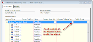
Click on the ellipsis button in the Change Volume Table column. This will bring up the Change Volume Tables dialog box. In this dialog box I want to select Total Volume from the Type drop-down. I want to select the Table style to use, in this case I am using the Basic Style. Click the Add button to add the table definition. Then I want to make sure that I select the corresponding Material List from the pull-down in the table definition. Then I can set the location of the table using the section view and table anchors.
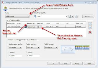 Then click on OK and you should have your volume tables attached to each of the cross sections. One caveat here is that when you add the Volume Tables to existing cross sections, you will probably have to go back and edit the spacing of your sections. So, you may have a little more work to do, but it is automated by editing the Section View Group and the Array on your Group Plot Style. Remember that you can create the Volume tables as you create the Cross Section Views, but you have to compute the materials before creating the views. Here is an image of a completed section with a volume table.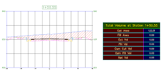
Subscribe to:
Posts (Atom)