


Hey everyone! I've got a couple of things to talk about today. The first is Autodesk University 2008. The event will be held December 2-5, 2008 at the Venetian in Las Vegas. If you have never been, I suggest that you do everything possible to attend. Autodesk University (AU) is a meeting of the best and brightest Autodesk users from around the world. There are learning tracts for all industries including Civil and GIS. The classes are typically 90 mins long and some of them are actually hands on labs where you can work through exercises in the software. A lot of the classes will gain you some valuable Continuing Education credits!
The registration fee includes the cost of the conference, breakfast and lunch during the conference and Autodesk sponsored events during the evenings. The instructors are from Autodesk and Resellers across the country. In fact two of the presenters are from Alacad! Check it out. Here is the link: http://au.autodesk.com/
Okay, now for topic number two. I am currently trying to produce courseware for our surveying customers. I have not been able to locate any training materials that will help our surveyors in their day-to-day operations. If your company is willing to donate survey data to the cause please reply here and I will get back to you. I am in need of raw data files for traverses and topos.
The courseware that I am trying to write will cover data collection methods, using the Autodesk Field Book format to insert data and line work, or Field to Finish, creating plat maps, surfaces and the creation and use of parcels. These topics are what I see as the typical things that surveying customers are looking for. I am also open to further suggestions as to what this class should contain. Again reply to this post.
Thursday, October 9, 2008


Friday, September 19, 2008
Transparent Hatches
Hey folks! It has been a while again. I have been traveling quite a bit as of late and haven't taken the opportunity to write. I wanted to share something that I came across yesterday morning. I was trolling the Autodesk Civil 3D website and downloaded Luy Kuhn's "Tips and Tricks" webcast. While watching the webcast a support call came to mind. I received a call some time ago about creating transparent hatches. A customer had an aerial photograph that he had referenced into a drawing and was wanting to put some solid color fills in certain areas for a presentation he was doing. The problem was that the solid fill hatches came out as solid color blobs on his plot. Definitely not what he was looking for. We tried various things to get it to work to no avail. We finally gave up and decided that it couldn't be done very easily.
Well, have I got something for you! As I said I had been watching the webcast and Lucy decided to show how to create a transparent hatch. The method involves using the shrinkwrap command to create a closed polyline around a hatch pattern. Then the pattern is erased and the shapes are exported as SDF data. Using FDO Connect in Map 3D the data was queried into the drawing and a theme was applied to it. In Map 3D you can change the transparency of a theme by moving a slider bar! It was definitely easier than anything I had seen or tried.
If you want to see a clip of Lucy creating these transparent hatches peruse over to the Autodesk Civil 3D website and click on the Civil 3D Resource Center Link. You will have to register to view the content, but I think it will be worth it. There are other short vids of Lucy showing different functionalities of Civil 3D. A lot of information can be found there. Take a look when you get a chance!
Well, have I got something for you! As I said I had been watching the webcast and Lucy decided to show how to create a transparent hatch. The method involves using the shrinkwrap command to create a closed polyline around a hatch pattern. Then the pattern is erased and the shapes are exported as SDF data. Using FDO Connect in Map 3D the data was queried into the drawing and a theme was applied to it. In Map 3D you can change the transparency of a theme by moving a slider bar! It was definitely easier than anything I had seen or tried.
If you want to see a clip of Lucy creating these transparent hatches peruse over to the Autodesk Civil 3D website and click on the Civil 3D Resource Center Link. You will have to register to view the content, but I think it will be worth it. There are other short vids of Lucy showing different functionalities of Civil 3D. A lot of information can be found there. Take a look when you get a chance!
Friday, August 22, 2008
Those Pesky Pipe Slope Labels
Wow, has it been almost a month since my last post? Eh, life on the road! Anyway I was visiting with a customer yesterday who was somewhat aggrevated about the way Civil 3D labels pipes, inverts and slopes.
I tried to explain to him that the software is setup to compute pipe lengths and slopes based on the starting and ending points of the pipe. This means that the slope is computed from center of structure to center of structure. Being from the same geographical region as my customer and having dealt with most of the same regulating agencies, I felt his pain. You see, in our area the reviewing agencies require a 0.10' drop across a sanitary sewer manhole and 0.20' drop if the angle is 9o degrees. This drop across the manhole is measured from the invert of the pipe coming in to the manhole to the invert of the pipe going out of the manhole. I explained that Civil 3D, as well as all of the other civil engineering software packages that I have used in the past, calculate the slope of a pipe from the center of a structure to the center of the next structure. Herein lies the problem. The reviewing agencies look at the inverts and the lengths of the pipe and check the slope. Well, if I give them the length of pipe and it is the same as the distance between the manholes they start questioning the design. Or, if I give them the face to face length of pipe and the inverts, the slope doesn't match the computed value. So, what is the sloution?
After scouring articles and discussion groups on the internet I had decided that most of the people that had written on this subject had come up with the best solution. But as i met with my customer yesterday we had a little brain storm. Why not use an expression to calculate the desired slope? We tried it and, hey it worked! We got our desired results!
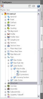
Here is what we did. Since the regulating agency expects to see the inverts, face to face pipe length and the slope we created an expression. I would suggest creating this expression in your standard template file so that you don't have to recreate it with each new project. First click on the Stettings tab in Toolspace. Then go down to Pipe and expand the node. Then expand the Label Styles node and expand the Plan Profile node. Here you will see an item called Expressions.
Right click on Expressions and select New. This will bring up a dialog box that looks similar to a scientific calculator. Be careful here when selecting a name for the Expression that you are
 creating. Once you create the the Expression, you cannot edit the formula or change the name. So, be careful and pay attention to what you are doing. For this expression, we chose a name of Slope face to face. Then we added the components to our expression. In the figure above you see the keypad that looks very similar to a calculator. To the right are two radio buttons. The first button is a list of available "variables" that can be used in your expression. The second button contains a list of mathematical fucntions that may be included in your calculations.
For our Expression we added in the the following formula:
({Start Invert Elevation}-{End Invert Elevation})/{2D Length - To Inside Edges}
Then we changed the Format result as: box to Percent, since that is the solution that we are looking for.
Once the expression is created you have to go into your Pipe Label Style and change the style to contain the new "Slope face to face" label and change the pipe length to the 2D - inside edge to inside edge. This should fix the label issue. The only issue that remains, and I haven't come up with a solution for it yet, is that in the profile view, if you measure from the point of intersection of the inside pipe diameter line and the side of the box to the nearest grid line and calculate that elevation, the elevation of the pipe will be off by a couple of hundredths for flat slopes. This should not be an issue since this is a graphical representation.
Have fun with Pipes!
Monday, July 28, 2008
Label Styles - Anchors and Attachments
In the past few weeks I have had several people asking about label styles and how to place the text in the correct place with relation to an object. For starters I would look at some of the label styles that ship with AutoCAD Civil 3D templates. These can be a great place to start looking for styles that may be modified to meet your company's standards.
 This will bring up the Label Style Composer Dialog box. On the Information tab give your new style a name. Click on the General Tab. Here you can set the text style, visibility and layer for you new point label style. (Hint: In 2009 the Standard Text Style maps to the Simplex font.) Next click on the Layout Tab. This is where all of the fun begins! The very first thing that you will see is a pull down menu called Component Name. To the right there are four buttons. These buttons are: Create Component, Copy Component, Delete Component and Component Draw Order. Click on the Create Component pull-down. You have options for creating text, line and block components. Choose Text to create a text component. Since we are dealing with Point Label Stlyes there will be three components present in the Component Name pull-down.
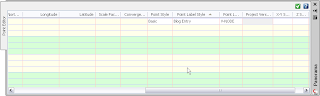
But, what if you can't find a style to modify to look like the particular label that you want? Well, that's when we get to be a little creative. Let's take a look at creating a Point Label Style. For Visual effect create a point using the create points command from the Points menu. Accept all of the defaults when creating the point. Then click on the point, right-click and select edit points. This brings up the Point Editor Panaorama Vista. Scroll over to the right until you see the columns labeled Point Style and Point Label Style. When you first select the point and scroll to the columns listed above the fields will probably be blank, unless you have specified a particular point style or point label style.
Click in the field for Point Style. This will bring up the Select Point Style Dialog box. Choose Basic from the pull-down menu and then select Edit Current Style from the button to the right of the pull-down menu. Change the marker style to "X" by clicking on the "X" button under Use Cutom Marker. Then click OK twice to get back to the Points Editor.
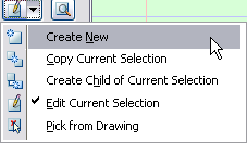
Next Click in the field for Point Label Style. This will bring up the Select Label Style Dialog Box. In this dialog box click the down arrow to the right of the button and Select Create New.
This will bring up the Label Style Composer Dialog box. On the Information tab give your new style a name. Click on the General Tab. Here you can set the text style, visibility and layer for you new point label style. (Hint: In 2009 the Standard Text Style maps to the Simplex font.) Next click on the Layout Tab. This is where all of the fun begins! The very first thing that you will see is a pull down menu called Component Name. To the right there are four buttons. These buttons are: Create Component, Copy Component, Delete Component and Component Draw Order. Click on the Create Component pull-down. You have options for creating text, line and block components. Choose Text to create a text component. Since we are dealing with Point Label Stlyes there will be three components present in the Component Name pull-down.In the field for Name under the General Node give your text component a name. For instance let's create a component for the Northing of the point. So we name the new component "Northing." We will leave the visibility set to true so that we can see the new component. The next field assigns the anchor component. Now, If we are creating a breand new label and we have no other text components in the style, we will have to anchor the new text component to the feature. If we have other text components we may choose to anchor to the feature or one of the other text components. When we have decided what to anchor our new text component to, we have to choose the anchor point.
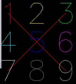
The screen capture above shows the nine possible anchor points associated with our point object. The anchor points are: Top Left, Top Center, Top Right, Middle Left, Middle Center, Middle Right, Bottom Left, Bottom Center and Bottom Right. The same nine anchor points are available if we choose to anchor our new text to an existing text component also. Just remember that each of the text components that we create also have attachment points that correspond to the nine positions shown above. So, what does that mean for us? That gives us a multitude of options for creating our labels.
Some other options for our labels are that we can use the x- and y-spacing to offset the attachment point from the anchor point if we need more space between the label and the object. (Think station labels.) We can also add rotation angles into the label style. The thing to watch out for here is that if we rotate the text component that is attached to the feature, we do not rotate the text components attached to that particular text component.
This is an overview of creating a point label. Be adventurous and explore the options for other types of labels.
Monday, July 14, 2008
Grading Short Course Notes Part 3
Okay, let's finish this site. The first thing we need to do is create a new site. We will do this the same way we created the Temporary site in the Part 2 of these notes. We will change the name of this site to "Final Site."
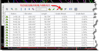
The Select Surface dialog box will appear. Select the Temporary Surface that we created in Part 2. You will notice that the elevation for each vertice is updated. If, by chance, your Temporary Surface does not encompass the feature line you will have some vertices that have a zero elevation. This can be fixed by assigning an elevation to those vertices in the elevation editor or you can use the "Set Grade/Slope Between Points" icon from the Feature Lines Toolbar. If you use the "Set Grade/Slope Between Points" command, you will be asked to select the starting point and elevation and the ending point and Grade/Slope/Elevation. (Just follow the prompts on the command line.)
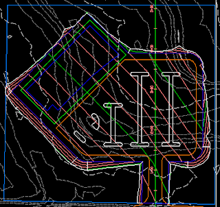
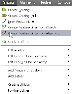
Next, we will click on the Grading menu at the top of the screen and select "Create Feature Lines from Objects." Select the poly line that surrounds the parking lot and building pad. The Create Feature Lines dialog box will open. We want to make sure that our site is set to Final Site. If it is not, select it from the pull down menu. We will set the style of our feature line to Basic, and make sure that we are on the C-TOPO-FEAT layer. Select the feature line that we just created and right-click. Select "Elevation Editor." From the tool bar select the Elevations from Surface icon.
The Select Surface dialog box will appear. Select the Temporary Surface that we created in Part 2. You will notice that the elevation for each vertice is updated. If, by chance, your Temporary Surface does not encompass the feature line you will have some vertices that have a zero elevation. This can be fixed by assigning an elevation to those vertices in the elevation editor or you can use the "Set Grade/Slope Between Points" icon from the Feature Lines Toolbar. If you use the "Set Grade/Slope Between Points" command, you will be asked to select the starting point and elevation and the ending point and Grade/Slope/Elevation. (Just follow the prompts on the command line.)
Next we will select "Create Grading" from the Grading Menu. On the Grading Creation Tools Toolbar we are going to select the leftmost icon to set the grading group. In the Site Name pull down menu we will select our Final Site. Then to the right of the Grading Group Name pull down you will see two (2) icons. We will select the icon on the far right - the "Create Grading Group" icon. In the Create Grading Group dialog box enter the name of Parking, select the Automatic surface Creation box and select the Use the Group Name check box. Then click "OK."
Back on the Grading Creation Tools toolbar we want to select the "Set Surface" icon, second from left, and set the surface to EG. Next we will set the Grading Criteria to "Grade to Surface." you will be asked to select a feature line. Select the feature line to which we set the elevations from our Temporary Surface. When prompted to select a side to grade, pick outside of the feature line, i.e an area that is not inside the parking lot or building footprint. You will be prompted to apply the grading to the entire length. Enter "NO." When prompted for a starting point use your endpoint OSNAP to select the endpoint of the feature line on the right side of the driveway at the entrance to the site. When prompted for the end point select the endpoint on the west side of the driveway. Follow the prompts on the command line. If you desire to change the cut or fill slope go ahead. I used a 5:1 cut and a 6:1 fill slope in my example. The grading limits and proposed contours should be shown on the screen.
Go back to the Grading Menu and select "Create Infill." Pick a point inside the parking lot to create the infil. This should connect the contour lines accross the parking area.
The screen capture above shows the site with the tie-in grading and infill grading through the parking lot.
Next, we will create feature lines from the outlines for the islands in the parking lot. Select one of the islands and right-click. Select "Select Similar" from the pop-up menu. Click on the Grading Menu and select "Create Feature Lines from Objects." In the Create Feature Lines dialog box set the style to "Bottom Curb," select the Erase Existing Entities check box and select the Assign Elevations check box. Click "OK." In the Assign Elevations dialog box change the surface to Parking and click OK. Click on the Grading Menu and select "Create Infill." click inside each island to create an infill for the islands.
A warning here... You will probably have to go back and create another infill for the parking area. When I stepped through this exercise, the centroid of the infill grading that I created after tying my parking surface into the EG suface fell inside one of my islands. That is not an issue, you may just have to create another infill for the rest of the parking lot.
Now let's click on the Grading menu and place our mouse over "Edit Feature Line Geometry." You should get a fly-out menu. Select "Stepped Offset" from that menu. We will now offset the curb feature lines to the inside a distance of 0.5 feet and an elevation difference of 0.5 feet.
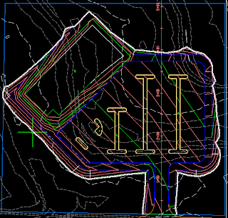
We need to create a feature line from the polyline that represents the edge of pavement for the parking lot. When creating the feature line, assign elevations from the parking surface. Then using the same commands create an offest of the edge of pavement o.5 feet to the outside and o.5 feet elevation difference. This will create a curb around the parking area. The only step left is to create a feature line for the building and assign an elevation to it. Again, you may have to create another infill for the area bounded by the tie-in grading, the building pad and the back of the curb around the parking area. When you have completed these steps, you should have something that looks like this:
The only thing left to do here is create our detention facility. I am going to leave that to your imagination.
Tuesday, July 8, 2008
Grading Short Course Notes Part 2
In the last post we created an existing ground surface, inserted the layout into the drawing file and exploded the block, created an alignment and profile from the polyline that runs north and south through the entrance of the site.
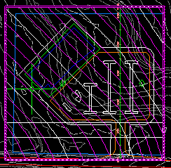 Your site should look similar to the image above. This concludes Part 2 of the Grading Short Course notes. Next time we will complete the grading of our site.
Now, we want to create a preliminary surface to assign elevations to some of the feature lines that we will use to create our final grading surface. We will start by creating a new site. Right-click on Sites in Toolspace and select "New." In the dialog box we are going to change the name to "Temporary."
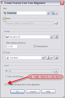
Let's create a feature line from the alignment that we created last time. From the Grading pull-down menu we will select "Create Feature Lines from Alignment." Selecting the alignment in the drawing will bring up the Create Feature Line from Alignment dialog box.
In the Create Feature Line from Alignment dialog box we want to make sure that the site is "Temporary." Next we will select the design profile that we created last time and wew want to make sure that the "Create Dynamic Link to the Alignmnet" box IS checked.
After we click OK, the Weed Vertices dialog box will appear. We will accept the default settings for now. Now we will create the temporary surface. Click on the Grading menu at the top of the screen and select "Create Grading." This will activate the Grading Creation Tools Toolbar. On the Grading Creation Tools Toolbar we will select the leftmost icon. This is the Create Grading Group icon. The Create Grading Group dialog box will appear.
In the Create grading dialog box we will type in the name "Temporary Surface." Next, select the Automatic Surface Creation check box, select the Use the Group Name check box and change the surface style if you want to. Finally, we will click OK to create the Grading Group and click OK to create the surface.
On the Grading Creation Tools Toolbar we will set the grading criteria to "Grade to Distance." We will create two gradings here. First, select the feature line and select the right side as the side to grade to. Accept the default answer of "Yes" when prompted to apply to entire length. On the right side we will grade to a distance of 150 feet. When the command line prompts for a grade or slope, type in G for grade and hit enter. Use a grade of 3.00%. On the left side we will grade to a distance of 400 feet at a grade of -2.00%.
Your site should look similar to the image above. This concludes Part 2 of the Grading Short Course notes. Next time we will complete the grading of our site.Wednesday, July 2, 2008
Grading Short Course Notes Part 1
Wow! I want to thank everyone that showed up for Alacad's first Short Course for Civil 3D users in the Mobile Area! The turn out was fabulous. Thank you all for participating and asking questions that I know others were wanting to ask. Okay....enough of the niceties, let's get to the dirt!
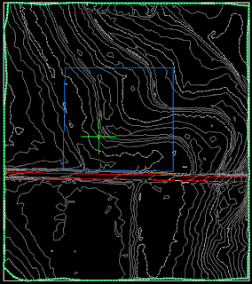
This short course walked through one method of grading a small commercial site with a building and parking areas. At the end we added a detention facility, too. To get started we had a drawing that consisted of an Existing Surface from an aerial photograph.
Now, if you will recall I talked about one of the new features for creating surfaces in AutoCAD Civil 3D 2009. That new feature is a Data Clip Boundary. When creating a surface from a large data set we create the Data Clip Boundary as the first operation. Then as we add data to our surface, i.e. points, point groups, breaklines, etc., the software will check the data to see if it falls inside the limits of the Data Clip Boundary. If the data is outside the boundary it is ignored.
Once we have our existing ground surface created, it is time to do some fun stuff! The next thing was to import the layout for the site as shown below.

Next, we created an alignment from the polyline that runs north and south through the parking lot. In creating the alignment we did not place the alignment on a site and we gave it a name of baseline. This makes it easier when creating the preliminary surface. Then we created an EG profile and profile view of the alignment. Next we create our design profile. This profile can be created with tangents only, or you could include vertical curve data.
Join me next time for Part 2 of the Grading Short Course notes.
Subscribe to:
Posts (Atom)