Wow, has it been almost a month since my last post? Eh, life on the road! Anyway I was visiting with a customer yesterday who was somewhat
aggrevated about the way Civil 3D labels pipes, inverts and slopes.
I tried to explain to him that the software is setup to compute pipe lengths and slopes based on the starting and ending points of the pipe. This means that the slope is computed from center of structure to center of structure. Being from the same geographical region as my customer and having dealt with most of the same regulating agencies, I felt his pain. You see, in our area the reviewing agencies require a 0.10' drop across a sanitary sewer manhole and 0.20' drop if the angle is 9o degrees. This drop across the manhole is measured from the invert of the pipe coming in to the manhole to the invert of the pipe going out of the manhole. I explained that Civil 3D, as well as all of the other civil engineering software packages that I have used in the past, calculate the slope of a pipe from the center of a structure to the center of the next structure. Herein lies the problem. The reviewing agencies look at the inverts and the lengths of the pipe and check the slope. Well, if I give them the length of pipe and it is the same as the distance between the manholes they start questioning the design. Or, if I give them the face to face length of pipe and the inverts, the slope doesn't match the computed value. So, what is the sloution?
After scouring articles and discussion groups on the internet I had decided that most of the people that had written on this subject had come up with the best solution. But as i met with my customer yesterday we had a little brain storm. Why not use an expression to calculate the desired slope? We tried it and, hey it worked! We got our desired results!
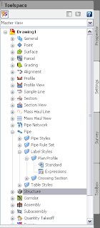
Here is what we did. Since the regulating agency expects to see the inverts, face to face pipe length and the slope we created an expression. I would suggest creating this expression in your standard template file so that you don't have to recreate it with each new project. First click on the Stettings tab in Toolspace. Then go down to Pipe and expand the node. Then expand the Label Styles node and expand the Plan Profile node. Here you will see an item called Expressions.
Right click on Expressions and select New. This will bring up a dialog box that looks similar to a scientific calculator. Be careful here when selecting a name for the Expression that you are
 creating. Once you create the the Expression, you cannot edit the formula or change the name. So, be careful and pay attention to what you are doing. For this expression, we chose a name of Slope face to face. Then we added the components to our expression. In the figure above you see the keypad that looks very similar to a calculator. To the right are two radio buttons. The first button is a list of available "variables" that can be used in your expression. The second button contains a list of mathematical fucntions that may be included in your calculations.
For our Expression we added in the the following formula:
({Start Invert Elevation}-{End Invert Elevation})/{2D Length - To Inside Edges}
Then we changed the Format result as: box to Percent, since that is the solution that we are looking for.
Once the expression is created you have to go into your Pipe Label Style and change the style to contain the new "Slope face to face" label and change the pipe length to the 2D - inside edge to inside edge. This should fix the label issue. The only issue that remains, and I haven't come up with a solution for it yet, is that in the profile view, if you measure from the point of intersection of the inside pipe diameter line and the side of the box to the nearest grid line and calculate that elevation, the elevation of the pipe will be off by a couple of hundredths for flat slopes. This should not be an issue since this is a graphical representation.
Have fun with Pipes!