We know that this is not correct. So, how do we fix it? It just so happens that there is a very simple fix to this issue. All we have to do is open up the Corridor Properties and click on the Surfaces Tab. In the table showing our surface definitions we see that there is a column called Overhang. This column is the correction for the jump in the surface shown above. This is what I had been missing!
 Here we can see that the Datum surface more closely resembles how a contractor would construct our roadway with a 1 foot extension of the sub-base under our curb and gutter.Now lets talk about material and earthworks volumes based on our cross sections. We are going to assume that at this point that we have created our cross sections from the alignment associated with our corridor model and that we have created multiple cross section views on a D-size sheet. At this point we realize that we forgot to add the volume tables to our cross sections. Can we fix this rather easily? You bet we can.
First of all we have to go to the Sections pull-down menu and select Compute Materials. Make sure that you select the Alignment for which you have cut cross sections and the Sample Line Group for that particular alignment. This will bring up the Compute Materials dialog box. In the Compute materials dialog box there is a drop-down for Quantity Takeoff Criteria. It depends on the final output that I am looking for as to which criteria I select. In this instance we are going to select Material List.
 At this point I will edit the Material List Criteria to make sure that have the materials listed that I am interested in, such as Pave1, Pave2, Base and Sub-base. After setting the materials that I want I click on OK to close the Compute Materials dialog. Next I go back to the Sections menu and select Compute Materials again.
 I want to click on the Import another criteria. This will allow me to add additional criteria to the current materials list. Here I want to select Earthworks so that we can calculate the cut/fill volumes at each section.

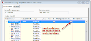
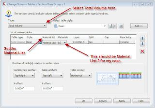
Click on the ellipsis button in the Change Volume Table column. This will bring up the Change Volume Tables dialog box. In this dialog box I want to select Total Volume from the Type drop-down. I want to select the Table style to use, in this case I am using the Basic Style. Click the Add button to add the table definition. Then I want to make sure that I select the corresponding Material List from the pull-down in the table definition. Then I can set the location of the table using the section view and table anchors.
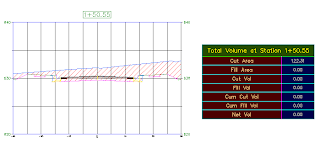
 Then click on OK and you should have your volume tables attached to each of the cross sections. One caveat here is that when you add the Volume Tables to existing cross sections, you will probably have to go back and edit the spacing of your sections. So, you may have a little more work to do, but it is automated by editing the Section View Group and the Array on your Group Plot Style. Remember that you can create the Volume tables as you create the Cross Section Views, but you have to compute the materials before creating the views. Here is an image of a completed section with a volume table.