Friday, May 14, 2010
This Blog Has MOVED!!!!!!!!!!
Hey everyone! I have decided to relocate this blog to a new location. The new location is http://gettingtothedirt.wordpress.com. You will have to register for an account at Wordpress if you want to leave a comment on the blog page, but the account is benign. I have had one for a while and have never received any spam or junk mail from my account there. Come on over and check out the new digs!
Monday, May 10, 2010
The Conditional Subassembly - Could it be Right for You?
I want to start this post by giving credit to Jason Hickey at Autodesk Support for suggesting that I look into the use of the Conditional Subassembly when trying to assist one of my customers a couple of weeks ago. I have to say what an asset Jason and the rest of the Civil 3D support team are! Thanks guys.
 The hardest thing to overcome when using the conditional subassembly is that the subassembly requires a Length and Slope as parameters. The length and slope are only used to place the conditional subaseembly and any subassemblies to be applied for that condition graphically on the screen, instead of having all of them stacked on top of each other. This makes selecting and editing the individual conditions easier for the user. Again, these length and slope parameters are not specifying a length and slope from the attachment point to a point where the subassemblies will be applied, but just placing them on the screen. The subassemblies will be applied at the connection point of the conditional subassembly.OK, now that I have described the conditional subassembly, let's take a look at how we can apply it. Let's assume that we have a roadway that we are designing or needing to model. We will build an assembly as usual, but when we get out to the daylight area we will have a couple of decisions to make. Let's assume that along our roadway if we have to cut more than three feet from the elevation at the edge of the outside boulevard of the sidewalk that we will be required to construct a retaining wall along our roadway. If we were to design this roadway without using the conditional assembly, it is conceivable that we could do this with one assembly, assuming that the height of wall and amount of cover are adjusted so that the retaining wall subassembly is not applied in areas where our cut is less than 3 feet from the outside boulevard elevation.
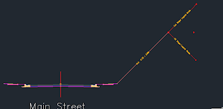
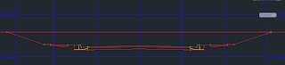
 Our assembly should resemble the image above. Now will will add the first conditional cut/fill subassembly to the right side. On the tool palette click on the conditional tab and then select the ConditionalCutOrFill subassembly. The Properties dialog will open and look something like this:
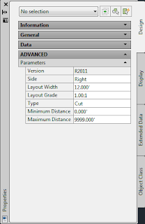
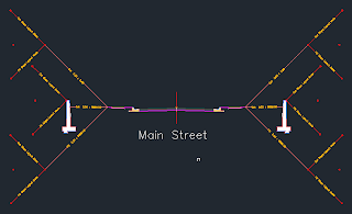
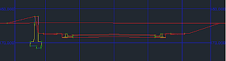
 Next we will add the condition for our retaining wall and the fill condition. When you are trying to figure out what the Layout Length and Layout Grade needs to be for your conditional subassembly, if it is a cut situation the parameters input will place the conditional subassembly above a horizontal projection from the connection point. If it is a fill condition that you are establishing, it will place the conditional below the horizontal projection from the connection point. So, after adding in the conditional subassemblies and copying all of the assemblies to the left side of our Assembly, we should have something like this:
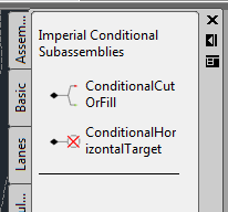
So, what is this Conditional Subassembly anyway? Well, if you ever had a course in computer programming you may remember the "If, Then" statement that placed conditions on your routine. (i.e. If x>0, then y=3x^2...) The Conditional Subassembly does the same thing for your Assembly and corridor model. The Conditional Subassembly comes in two varieties, one that targets horizontal alignments while the other targets cut/fill situations. (Note: for the rest of this post we will be looking at the Conditional Cut/Fill Subassembly.) There is no limit to the number of Conditional Subassemblies that can be applied to the Assembly. One of the neat things that you can do with this subassembly is apply it to other conditional subassemblies.
So, with a little planning and forethought upfront, you may be able to model a corridor with 1 or 1 assemblies instead of 5 or 6 or more. If you are an outside the box kind of thinker, then the possibilities of applying the conditional subassembly could be endless.
The hardest thing to overcome when using the conditional subassembly is that the subassembly requires a Length and Slope as parameters. The length and slope are only used to place the conditional subaseembly and any subassemblies to be applied for that condition graphically on the screen, instead of having all of them stacked on top of each other. This makes selecting and editing the individual conditions easier for the user. Again, these length and slope parameters are not specifying a length and slope from the attachment point to a point where the subassemblies will be applied, but just placing them on the screen. The subassemblies will be applied at the connection point of the conditional subassembly.OK, now that I have described the conditional subassembly, let's take a look at how we can apply it. Let's assume that we have a roadway that we are designing or needing to model. We will build an assembly as usual, but when we get out to the daylight area we will have a couple of decisions to make. Let's assume that along our roadway if we have to cut more than three feet from the elevation at the edge of the outside boulevard of the sidewalk that we will be required to construct a retaining wall along our roadway. If we were to design this roadway without using the conditional assembly, it is conceivable that we could do this with one assembly, assuming that the height of wall and amount of cover are adjusted so that the retaining wall subassembly is not applied in areas where our cut is less than 3 feet from the outside boulevard elevation.But, our goal here is to make this as simple as possible. By applying the conditional subassembly we can define what happens in areas of cut from 0.00' to 3.00' above the outside boulevard elevation and then again for anything above 3.00' of cut. We will also define what happens in the fill situation. The roadway will be a typical two-lane road using the LaneOutsideSuper and UrbanCurbGutterGeneral subassemblies. We will then apply the UrbanSidewalk subassembly with an inside boulevard of 2.5', sidewalk width of 4', depth of 4", an outside boulevard width of 1.5' and a slope of 2%.
Our assembly should resemble the image above. Now will will add the first conditional cut/fill subassembly to the right side. On the tool palette click on the conditional tab and then select the ConditionalCutOrFill subassembly. The Properties dialog will open and look something like this:Notice the parameters for Layout Width and Layout Grade. These are the parameters that are going to locate the Conditional Cut or Fill subassembly in relation to the edge of the outside boulevard of our sidewalk subassembly. We are going to enter a Layout Width of 20 and a Layout Grade of 1:1. Then we will change the Maximum Distance to 2.99' and attach this subassembly to the marker at the right edge of the Outside Boulevard. Then we will add the BasicSideSlopeCutDitch Subassembly to the end of the CondtionalCutOrFill Subassembly after changing the parameters for the Cut Ditch subassembly by reducing the Foreslope and Backslope widths to 0.00 and the slope for the Cut to 3:1. The result looks like this:
Next we will add the condition for our retaining wall and the fill condition. When you are trying to figure out what the Layout Length and Layout Grade needs to be for your conditional subassembly, if it is a cut situation the parameters input will place the conditional subassembly above a horizontal projection from the connection point. If it is a fill condition that you are establishing, it will place the conditional below the horizontal projection from the connection point. So, after adding in the conditional subassemblies and copying all of the assemblies to the left side of our Assembly, we should have something like this:Now we can create our corridor model and set the target for all of the daylight assemblies to Existing Ground. There may be a need to change how often the assembly is applied to the corridor to help get an accurate location for the transition from from a cut slope to the retaining wall. If you have those stations established, you could just add them in as supplemental stations.
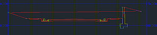
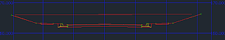
After the corridor has been created, we can look at the corridor sections to see if the corridor model applied the conditions correctly. Below are some screen captures from the station immediately prior to transitioning to the retaining wall and from the retaining wall to a cut section.
Happy Modeling!
Monday, March 29, 2010
AutoCAD Civil 3D 2011
Last week Autodesk officially announced its 2011 portfolio of products. Some of those products are available on the Subscription Center. With this year's releases, downloading from the Subscription Center is the primary way to get you software now. But, you can click on a link there and request media.
Now, I don't have a lot of time this morning but, I want to leave you with one thing about the upcoming release...........64-bit! Yes, that is right. This year's release of AutoCAD Civil 3d will be released in 32-bit and 64-bit.
I will be posting some more information in the coming days.
Now, I don't have a lot of time this morning but, I want to leave you with one thing about the upcoming release...........64-bit! Yes, that is right. This year's release of AutoCAD Civil 3d will be released in 32-bit and 64-bit.
I will be posting some more information in the coming days.
Thursday, December 10, 2009
1 Day Grading Course in Madison, MS
Hey everyone! I just wanted to let you all know that ALACAD will be having a 1-day Grading Course on January 28, 2010 in our Madison, MS office. Space is limited and is first come first served. For more information follow this link!
Here is a brief description of the class.
Here is a brief description of the class.
This 1-day course will cover several options for grading and show the user how to utilize the different grading techniques to their advantage. Grading in Civil 3D is probably one of the most powerful functionalities in the software, but is also one of the least understood.
This course will begin with a discussion of some basic properties of a surface in Civil 3D and how to modify the surface. This will include a discussion on the methodology Civil 3D uses for creating a TIN. In addition, we will cover the definition and use of Feature Lines. Finally, we will look at some methods for creation grading plans, or finished grade surfaces using the different tools at our disposal.
Thursday, October 22, 2009
Autodesk Releases Subscription Advantage Packs for Many Software Titles
Does it really pay to be an Autodesk Subscription Customer? After a brief review of the Subscription Advantage Packs released yesterday I believe the answer has to be a resounding, "YES!!!!!!!" The Advantage Pack for Civil 3D 2010 has many tools that will help increase productivity and efficiency. Let's take a look at some of the new tools that are in the Advantage Pack.
The tools are organized into groups in the Subscription Extension Manager on the Toolbox tab in Toolspace. The first category is for Alignments. There are 2 tools here. The first will allow the user to create a new alignment from an existing alignment and add data to the newly created alignment. (Think rail switches.) This tool can be used in other ways such as creating alternative alignments that have common tie-ins. The next tool for alignments is a routine that will create a best fit alignment from point data. Invoke the routine and pick a point group and you are off to the races! You will be shown a report of the best fit analisys.
The next category contains some inquiry tools for computing minimum distances between entities and surfaces and vertical distances between entities.
Next is Point Clouds. Finally Civil 3D has tools to allow us to harness LiDAR data! The Point Cloud routine will allow you to create a Point Cloud database (.isd format) from data in several different formats. Once the database is created you can recall the point cloud database using the same wizard from the Toolbox tab in toolspace. You can stylize the point cloud to show the information that you want to see and then you can also remove the Civil 3D settings from the point cloud so that the data can be used as a default subset of points.
The next group is for points. The new tool here is not really new, but there is a zoom to command here that allows you to input the point number without having to find the point in a point group first. The really cool thing is that this command can be run as a transparent command!
The Profile group has a routine for creating a best fit profile from COGO point data, surface profiles, feature lines or AutoCAD 3D polylines, points or blocks.
The next tool is for laying out Roundabouts. This routine has a wizard that asks for design criteria and then lays out the roundabout for you based on the alignment geometry and data input into the wizard.
There are some other tools that I will let you discover on your own. So, If you are a Subscription customer, go to the Subscription Center and download the Advantage Pack today. I think it is well worth it. While you are there, watch the video clip. It gives an overview of some of these tools in action. If you are not a Subscription member, call your Reseller today and purchase your annual Subscription to Civil 3D so that you can have access to these great new tools too!
An Update to AutoCAD Civil 3D 2010 and Windows 7
It has been a little over 2 weeks since upgrading my OS to Windows 7. So far I have not run into any issues when working in AutoCAD Civil 3D. The software seems to load quicker and respond quicker in most cases. I have had two crashes since installing OS. The first was a BSOD, but I was pushing the OS with Civil 3D, several Office programs, IE and a couple of Virtual Machines running. As best I could tell the crash was actually caused by a driver that I hadn't updated. After updating the driver the only other crash was actually in Civil 3D, but could be attributed to User Error!
Tuesday, October 6, 2009
Civil 3D and Windows 7
Ok.....I believe in living on the bleeding edge! Last night I decided to install Windows 7 and see what happened. So far, so good. The only thing that I found was something that has been going on for a while. If you prefer to use Firefox as your web browser, you will probably not be able to have the reporting feature in Civil 3D open directly in the browser. This is an old issue. I tried to set IE as the default browser and map .htm and .html files to Firefox, but I still kept getting an error. As soon as I deleted Firefox I was able to get the reports to open in a browser window. Not sure that I am happy about that. I kinda like Firefox. The other option is to create a shortcut on your desktop that maps to the CivilReport.html file so that you can run the report and then click the shortcut and have it open in Firefox. Just a couple of more clicks I guess, but I would like to be able to use whatever browser I choose.
Subscribe to:
Posts (Atom)