Friday, May 14, 2010
This Blog Has MOVED!!!!!!!!!!
Hey everyone! I have decided to relocate this blog to a new location. The new location is http://gettingtothedirt.wordpress.com. You will have to register for an account at Wordpress if you want to leave a comment on the blog page, but the account is benign. I have had one for a while and have never received any spam or junk mail from my account there. Come on over and check out the new digs!
Monday, May 10, 2010
The Conditional Subassembly - Could it be Right for You?
I want to start this post by giving credit to Jason Hickey at Autodesk Support for suggesting that I look into the use of the Conditional Subassembly when trying to assist one of my customers a couple of weeks ago. I have to say what an asset Jason and the rest of the Civil 3D support team are! Thanks guys.
 The hardest thing to overcome when using the conditional subassembly is that the subassembly requires a Length and Slope as parameters. The length and slope are only used to place the conditional subaseembly and any subassemblies to be applied for that condition graphically on the screen, instead of having all of them stacked on top of each other. This makes selecting and editing the individual conditions easier for the user. Again, these length and slope parameters are not specifying a length and slope from the attachment point to a point where the subassemblies will be applied, but just placing them on the screen. The subassemblies will be applied at the connection point of the conditional subassembly.OK, now that I have described the conditional subassembly, let's take a look at how we can apply it. Let's assume that we have a roadway that we are designing or needing to model. We will build an assembly as usual, but when we get out to the daylight area we will have a couple of decisions to make. Let's assume that along our roadway if we have to cut more than three feet from the elevation at the edge of the outside boulevard of the sidewalk that we will be required to construct a retaining wall along our roadway. If we were to design this roadway without using the conditional assembly, it is conceivable that we could do this with one assembly, assuming that the height of wall and amount of cover are adjusted so that the retaining wall subassembly is not applied in areas where our cut is less than 3 feet from the outside boulevard elevation.
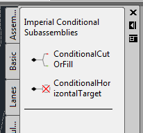
 Our assembly should resemble the image above. Now will will add the first conditional cut/fill subassembly to the right side. On the tool palette click on the conditional tab and then select the ConditionalCutOrFill subassembly. The Properties dialog will open and look something like this:
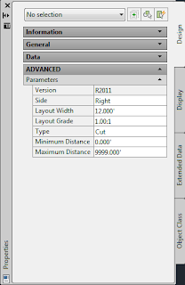
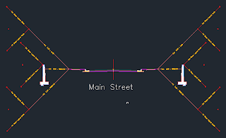
 Next we will add the condition for our retaining wall and the fill condition. When you are trying to figure out what the Layout Length and Layout Grade needs to be for your conditional subassembly, if it is a cut situation the parameters input will place the conditional subassembly above a horizontal projection from the connection point. If it is a fill condition that you are establishing, it will place the conditional below the horizontal projection from the connection point. So, after adding in the conditional subassemblies and copying all of the assemblies to the left side of our Assembly, we should have something like this:
So, what is this Conditional Subassembly anyway? Well, if you ever had a course in computer programming you may remember the "If, Then" statement that placed conditions on your routine. (i.e. If x>0, then y=3x^2...) The Conditional Subassembly does the same thing for your Assembly and corridor model. The Conditional Subassembly comes in two varieties, one that targets horizontal alignments while the other targets cut/fill situations. (Note: for the rest of this post we will be looking at the Conditional Cut/Fill Subassembly.) There is no limit to the number of Conditional Subassemblies that can be applied to the Assembly. One of the neat things that you can do with this subassembly is apply it to other conditional subassemblies.
So, with a little planning and forethought upfront, you may be able to model a corridor with 1 or 1 assemblies instead of 5 or 6 or more. If you are an outside the box kind of thinker, then the possibilities of applying the conditional subassembly could be endless.
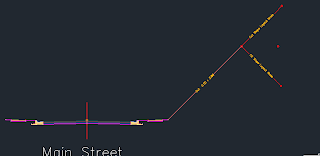
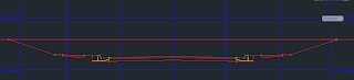
The hardest thing to overcome when using the conditional subassembly is that the subassembly requires a Length and Slope as parameters. The length and slope are only used to place the conditional subaseembly and any subassemblies to be applied for that condition graphically on the screen, instead of having all of them stacked on top of each other. This makes selecting and editing the individual conditions easier for the user. Again, these length and slope parameters are not specifying a length and slope from the attachment point to a point where the subassemblies will be applied, but just placing them on the screen. The subassemblies will be applied at the connection point of the conditional subassembly.OK, now that I have described the conditional subassembly, let's take a look at how we can apply it. Let's assume that we have a roadway that we are designing or needing to model. We will build an assembly as usual, but when we get out to the daylight area we will have a couple of decisions to make. Let's assume that along our roadway if we have to cut more than three feet from the elevation at the edge of the outside boulevard of the sidewalk that we will be required to construct a retaining wall along our roadway. If we were to design this roadway without using the conditional assembly, it is conceivable that we could do this with one assembly, assuming that the height of wall and amount of cover are adjusted so that the retaining wall subassembly is not applied in areas where our cut is less than 3 feet from the outside boulevard elevation.But, our goal here is to make this as simple as possible. By applying the conditional subassembly we can define what happens in areas of cut from 0.00' to 3.00' above the outside boulevard elevation and then again for anything above 3.00' of cut. We will also define what happens in the fill situation. The roadway will be a typical two-lane road using the LaneOutsideSuper and UrbanCurbGutterGeneral subassemblies. We will then apply the UrbanSidewalk subassembly with an inside boulevard of 2.5', sidewalk width of 4', depth of 4", an outside boulevard width of 1.5' and a slope of 2%.
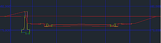
Our assembly should resemble the image above. Now will will add the first conditional cut/fill subassembly to the right side. On the tool palette click on the conditional tab and then select the ConditionalCutOrFill subassembly. The Properties dialog will open and look something like this:Notice the parameters for Layout Width and Layout Grade. These are the parameters that are going to locate the Conditional Cut or Fill subassembly in relation to the edge of the outside boulevard of our sidewalk subassembly. We are going to enter a Layout Width of 20 and a Layout Grade of 1:1. Then we will change the Maximum Distance to 2.99' and attach this subassembly to the marker at the right edge of the Outside Boulevard. Then we will add the BasicSideSlopeCutDitch Subassembly to the end of the CondtionalCutOrFill Subassembly after changing the parameters for the Cut Ditch subassembly by reducing the Foreslope and Backslope widths to 0.00 and the slope for the Cut to 3:1. The result looks like this:
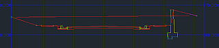
Next we will add the condition for our retaining wall and the fill condition. When you are trying to figure out what the Layout Length and Layout Grade needs to be for your conditional subassembly, if it is a cut situation the parameters input will place the conditional subassembly above a horizontal projection from the connection point. If it is a fill condition that you are establishing, it will place the conditional below the horizontal projection from the connection point. So, after adding in the conditional subassemblies and copying all of the assemblies to the left side of our Assembly, we should have something like this:Now we can create our corridor model and set the target for all of the daylight assemblies to Existing Ground. There may be a need to change how often the assembly is applied to the corridor to help get an accurate location for the transition from from a cut slope to the retaining wall. If you have those stations established, you could just add them in as supplemental stations.
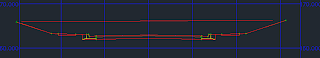
After the corridor has been created, we can look at the corridor sections to see if the corridor model applied the conditions correctly. Below are some screen captures from the station immediately prior to transitioning to the retaining wall and from the retaining wall to a cut section.
Happy Modeling!
Subscribe to:
Posts (Atom)