Friday, October 31, 2008
An Update to Transparent Hatches
Well, that got me to thinking and doing some more research on the topic. I called on Alacad's resident Map 3D specialist James Murphy. I told James the steps that I had gone through to create the "transparent hatch." I asked him the all important question of how can I get this transpaernt theme to hatch. James informed me of a command that is new to the 2009 version of Map 3D, which means that it also works in Civil 3D. The command is MAPPLOTTRANSPARENCY. When you enter this on the command line you have the option to turn it on or off. Turn the command on. I sent the current drawing file to my local printer and lo and behold, the hatched area printed transparently! To get this to work on your local/network printer/plotter, you may have to adjust the line merge properties of the printer/plotter. This setting can be changed through the printer properties button on the plot screen. I hope this helps! Happy plotting!
Thursday, October 9, 2008
A Couple of Things
The registration fee includes the cost of the conference, breakfast and lunch during the conference and Autodesk sponsored events during the evenings. The instructors are from Autodesk and Resellers across the country. In fact two of the presenters are from Alacad! Check it out. Here is the link: http://au.autodesk.com/
Okay, now for topic number two. I am currently trying to produce courseware for our surveying customers. I have not been able to locate any training materials that will help our surveyors in their day-to-day operations. If your company is willing to donate survey data to the cause please reply here and I will get back to you. I am in need of raw data files for traverses and topos.
The courseware that I am trying to write will cover data collection methods, using the Autodesk Field Book format to insert data and line work, or Field to Finish, creating plat maps, surfaces and the creation and use of parcels. These topics are what I see as the typical things that surveying customers are looking for. I am also open to further suggestions as to what this class should contain. Again reply to this post.
Friday, September 19, 2008
Transparent Hatches
Well, have I got something for you! As I said I had been watching the webcast and Lucy decided to show how to create a transparent hatch. The method involves using the shrinkwrap command to create a closed polyline around a hatch pattern. Then the pattern is erased and the shapes are exported as SDF data. Using FDO Connect in Map 3D the data was queried into the drawing and a theme was applied to it. In Map 3D you can change the transparency of a theme by moving a slider bar! It was definitely easier than anything I had seen or tried.
If you want to see a clip of Lucy creating these transparent hatches peruse over to the Autodesk Civil 3D website and click on the Civil 3D Resource Center Link. You will have to register to view the content, but I think it will be worth it. There are other short vids of Lucy showing different functionalities of Civil 3D. A lot of information can be found there. Take a look when you get a chance!
Friday, August 22, 2008
Those Pesky Pipe Slope Labels
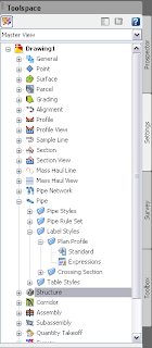
Right click on Expressions and select New. This will bring up a dialog box that looks similar to a scientific calculator. Be careful here when selecting a name for the Expression that you are
 creating. Once you create the the Expression, you cannot edit the formula or change the name. So, be careful and pay attention to what you are doing. For this expression, we chose a name of Slope face to face. Then we added the components to our expression. In the figure above you see the keypad that looks very similar to a calculator. To the right are two radio buttons. The first button is a list of available "variables" that can be used in your expression. The second button contains a list of mathematical fucntions that may be included in your calculations.
For our Expression we added in the the following formula:
({Start Invert Elevation}-{End Invert Elevation})/{2D Length - To Inside Edges}
Then we changed the Format result as: box to Percent, since that is the solution that we are looking for.
Once the expression is created you have to go into your Pipe Label Style and change the style to contain the new "Slope face to face" label and change the pipe length to the 2D - inside edge to inside edge. This should fix the label issue. The only issue that remains, and I haven't come up with a solution for it yet, is that in the profile view, if you measure from the point of intersection of the inside pipe diameter line and the side of the box to the nearest grid line and calculate that elevation, the elevation of the pipe will be off by a couple of hundredths for flat slopes. This should not be an issue since this is a graphical representation.
Have fun with Pipes!
Monday, July 28, 2008
Label Styles - Anchors and Attachments

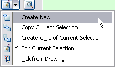 This will bring up the Label Style Composer Dialog box. On the Information tab give your new style a name. Click on the General Tab. Here you can set the text style, visibility and layer for you new point label style. (Hint: In 2009 the Standard Text Style maps to the Simplex font.) Next click on the Layout Tab. This is where all of the fun begins! The very first thing that you will see is a pull down menu called Component Name. To the right there are four buttons. These buttons are: Create Component, Copy Component, Delete Component and Component Draw Order. Click on the Create Component pull-down. You have options for creating text, line and block components. Choose Text to create a text component. Since we are dealing with Point Label Stlyes there will be three components present in the Component Name pull-down.
Monday, July 14, 2008
Grading Short Course Notes Part 3
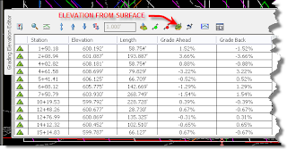
The Select Surface dialog box will appear. Select the Temporary Surface that we created in Part 2. You will notice that the elevation for each vertice is updated. If, by chance, your Temporary Surface does not encompass the feature line you will have some vertices that have a zero elevation. This can be fixed by assigning an elevation to those vertices in the elevation editor or you can use the "Set Grade/Slope Between Points" icon from the Feature Lines Toolbar. If you use the "Set Grade/Slope Between Points" command, you will be asked to select the starting point and elevation and the ending point and Grade/Slope/Elevation. (Just follow the prompts on the command line.)
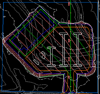
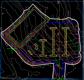
The only thing left to do here is create our detention facility. I am going to leave that to your imagination.
Tuesday, July 8, 2008
Grading Short Course Notes Part 2
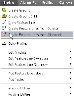
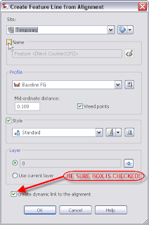
After we click OK, the Weed Vertices dialog box will appear. We will accept the default settings for now. Now we will create the temporary surface. Click on the Grading menu at the top of the screen and select "Create Grading." This will activate the Grading Creation Tools Toolbar. On the Grading Creation Tools Toolbar we will select the leftmost icon. This is the Create Grading Group icon. The Create Grading Group dialog box will appear.
In the Create grading dialog box we will type in the name "Temporary Surface." Next, select the Automatic Surface Creation check box, select the Use the Group Name check box and change the surface style if you want to. Finally, we will click OK to create the Grading Group and click OK to create the surface.
On the Grading Creation Tools Toolbar we will set the grading criteria to "Grade to Distance." We will create two gradings here. First, select the feature line and select the right side as the side to grade to. Accept the default answer of "Yes" when prompted to apply to entire length. On the right side we will grade to a distance of 150 feet. When the command line prompts for a grade or slope, type in G for grade and hit enter. Use a grade of 3.00%. On the left side we will grade to a distance of 400 feet at a grade of -2.00%.
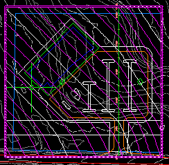 Your site should look similar to the image above. This concludes Part 2 of the Grading Short Course notes. Next time we will complete the grading of our site.
Wednesday, July 2, 2008
Grading Short Course Notes Part 1
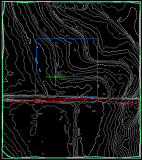
Now, if you will recall I talked about one of the new features for creating surfaces in AutoCAD Civil 3D 2009. That new feature is a Data Clip Boundary. When creating a surface from a large data set we create the Data Clip Boundary as the first operation. Then as we add data to our surface, i.e. points, point groups, breaklines, etc., the software will check the data to see if it falls inside the limits of the Data Clip Boundary. If the data is outside the boundary it is ignored.
Once we have our existing ground surface created, it is time to do some fun stuff! The next thing was to import the layout for the site as shown below.

Next, we created an alignment from the polyline that runs north and south through the parking lot. In creating the alignment we did not place the alignment on a site and we gave it a name of baseline. This makes it easier when creating the preliminary surface. Then we created an EG profile and profile view of the alignment. Next we create our design profile. This profile can be created with tangents only, or you could include vertical curve data.
Join me next time for Part 2 of the Grading Short Course notes.
Thursday, June 12, 2008
Grading Short Course
The seminar will consist of creating an existing ground surface, inserting a layout into the drawing and creating a site grading plan using the grading tools in Civil 3D 2009.
Register here.
Monday, June 9, 2008
FREE Higway and Road Design Seminar
Free Highway and Road Design Seminar in Huntsville, AL
Change is the only thing that is constant in Local Road design. Even the most minor design change can have a significant impact on the time you have to spend finishing a project. Valuable time that could be spent on better design is spent on costly re-work. Explore how you can save significant time and deliver higher quality designs with Autodesk Road Design solutions.
Join your peers for a free Executive Breakfast and hear about what's happening in transportation design around the country and in the southeast.
Tom Igou and Dave Fagerman of Autodesk's Government Division will share their industry knowledge and design backgrounds. Both bring more than 25 years to the highway & road design environment, including DOTs and local public works organizations. Register here.
Friday, June 20, 2008
Schedule:
8:00 - 8:30: Breakfast and Registration
8:30 - 8:45: Introduction and Welcome
8:45 - 10:00: Civil 3D in Transportation
10:00 - 10:15: Break
10:15 - 11:00: Civil 3D Demo
11:00: Wrap-up and Q&A
Heritage Club Huntsville111 Washington Street, NEHuntsville, AL 3801256-533-0350www.heritage-huntsville.com
Host: Jennifer Swoboda, ALACADJennifer.swoboda@alacad.com888-442-3100
Cost: FREE (registration required). Breakfast included!
Register here.
Field to Finish Seminar
Free Field to Finish Hands-on Workshop for Surveyors in Birmingham, AL
Spend the morning with ALACAD, an authorized AutoCAD Civil 3D reseller, and Earl Dudley Inc., an authorized Topcon Positioning dealer, for a fun and informative workshop presented by Autodesk Technical Expert Jerry Bartels that takes you from “Field to Finish” and demonstrates the new survey functionality in AutoCAD Civil 3D 2009. You will be able to experience this for yourself by surveying a section of the conference center using a Topcon data collector and then bringing those points inside AutoCAD Civil 3D for modeling.
For a true field to finish solution, Topcon with AutoCAD Civil 3D is the only choice.
Certificates of completion will be provided at the end of this workshop for claiming professional education credits. Register here.
8:00 am - 12:00 noon Thursday, June 19, 2008
Cahaba Grand Conference Center 1 Healthsouth Pkwy Birmingham, AL 35243
Presented by Jerry BartelsCivil Technical SpecialistAutodesk
Cost: FREE (registration required). Breakfast included!
Register here.
Getting Started
I am a graduate of the University of Alabama In Huntsville with a degree in civil engineering. I have been using AutoCAD products since the early 1990's. I am a Registered Professional Engineer in Alabama and Tennessee and have nearly 15 years experience in the "REAL WORLD." I have designed roadways, subdivisions and large and small commercial sites. I have always embraced technology and lived by the mantra of "work smarter, not harder." So, with that said I joined the staff at ALACAD in March of this year as an Applications Engineer specializing in Civil 3D. Now I have the opportunity to share what I have learned in using AutoCAD Civil 3D in a production setting.
Keep checking back as I plan to blog frequently, especially if I find a tidbit of info that I think is post-worthy.